Open the PixCon16 Configuration page by clicking the "Configure a PixCon16 controller" button on the Control Panel's Controller Setup section. Make sure your PixCon16 controller is powered on and that it and your computer are connected to the same Ethernet network (the Ethernet connector on the PixCon16 is the silver connector).
The PixCon16 is a little different than other Light-O-Rama controllers when it comes to configuration and use. All configuration of the board is done while it is connected to a standard LAN. The PixCon16 can not be configured via the LOR RS485 mode. The PixCon16 however can run (i.e. control lights) in either E1.31 mode (via an Ethernet network), or as an LOR device on an LOR ENHANCED network at 500K (1000k if there are only Pixie and/or PixCon16 controllers on the network). If you would like to use the PixCon16 as an LOR device, be sure to select 'LOR Mode', explained below. When in LOR mode, the PixCon16 can be connected to an MP3 Director (G3 or later) if desired.
Main Window
Click the "Search" button in the PixCon16 Utility. After a few seconds, a list of the PixCon16 / E1.31 devices that were found will be shown.

After pressing the Search button
To configure a particular board, double-click on it. The PixCon Configuration window should open.
Under some circumstances, the program may not be able to detect all of the controllers connected to your LAN. This can be due to multiple issues since the routing and configuration of TCP/IP can be tricky:
▪Most Importantly: Please select the correct network adapter at the top of the window. You must select the network adapter that is directly connected to the same network the PixCon16 is connected to.
▪The board may simply have missed the command for it to report in. Pressing "Search" again will usually find the missing controller. It could also be that the network is currently saturated with lighting commands. You should stop any running show before attempting to configure an E1.31 device.
▪If this is the first time you are configuring a board, or if you changed the configuration of your network, the device may no longer be at an IP that you are expecting. In that case, you may want to reset the board to factory specifications. This will then place the board into 'DHCP' mode where it will request an IP from your network. This requested IP should then be able to be found with the program. Please note that resetting the board will clear all of your configuration information, and you will need to re-configure the board.
After configuring you controller using the PixCon Configuration window, then clicking OK to save your configuration and close the window, the list of controllers in the main window will NOT automatically update. You will need to press the Search button again. Be patient -- it may take a few seconds for the controller to update its configuration and reboot before it is able to respond to a search request.
PixCon Configuration Window
Use this window to configure a specific PixCon16 controller. After changing the settings, click the "OK" button at the bottom of the screen to save the changes; otherwise, click "Cancel" to leave the device configuration unchanged.
The "PixCon Configuration" window has 5 tabs:
•LEDs
•Test
•Misc
Network Tab

The Network Tab
If you wish to let the controller be assigned an IP automatically by a router, select the ‘DHCP’ button. DHCP is the default mode of operation and will allow the controller to connect instantly to most home or corporate networks that have a router.
If you are connecting your controller directly to your PC or via a basic network switch on a network without a router, you will need to use a Static IP address.
To set a static address, select "Static" and then type in the IPV4 address you would like for the board, as well as the Subnet Mask. The address should be in the same range as the computer you are currently using to configure the board. The subnet mask should match the computer's as well. If you change the address to one that is not within the range of your local LAN, the board may 'disappear'. In that case you should reset the board to factory settings, search again for the board, and attempt to reconfigure it again.
Control Tab

The Control Tab
Mode of Operation (Ethernet Protocol)
The PixCon16 can be run in 3 different modes:
•As an E1.31 controller on an Ethernet network. The Ethernet cable should be connected to the silver connector on the PixCon16.
•As an Art-Net controller on an Ethernet network. This mode is not currently supported by the Light-O-Rama Software Suite.
•As an LOR device on an LOR RS485 network. A Cat5 cable is attached to the "J3/J4 (DMX #1)" jack on the board and run (directly or indirectly) to a Light-O-Rama USB adapter. Be sure to also move the jumpers on the board from the ESTA side to the LOR side near J4.
Start Universe / Channel
In E1.31 and Art-Net mode, these 2 fields specify the universe and start channel for the first port. Normally, the channel should be set to 1.
In LOR mode, this specifies the Unit Id and Circuit of the first port. Normally, the channel (circuit) should be set to 1. Note that the Unit Id here is in decimal (base 10), whereas the unit id is hexadecimal (base 16) in all other parts of the software. See the Unit Id Values topic for a conversion table.
Pixels Per Output
Enter the number of pixels on the longest string attached to this PixCon16.
DMX512 Outputs
This section allows you to enable/disable the 4 DMX ports available on the board, as well as assign the universe each will control. These ports act as a bridge between E1.31 and a DMX universe. By using one or more of these ports, you can eliminate the use of one or more USB DMX adapters. These ports are not active when using the board in LOR mode.
Advanced - OFF
If the "Advanced" box is not checked, then the start universe (or unit id) and channel for ports 2-15 will be automatically assigned.
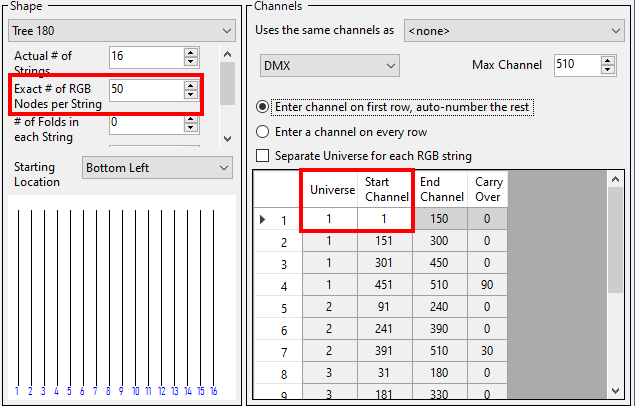
When using E1.31 mode and Advanced is off, then you should set up your Prop Definition similar to the following picture:
•Prop Definition's "Nodes per String" should match the PixCon16 Configuration "Pixels Per Output".
•Prop Definition's device type should be set to "DMX".
•Prop Definition's "Max Channel" should be set to 510.
•Prop Definition's Universe and Start Channel should match the corresponding PixCon16 Configuration.
•Prop Definition's "Enter channel on first row, auto-number the rest" should be selected.
•Prop Definition's "Separate Universe for each RGB string" should be unchecked.
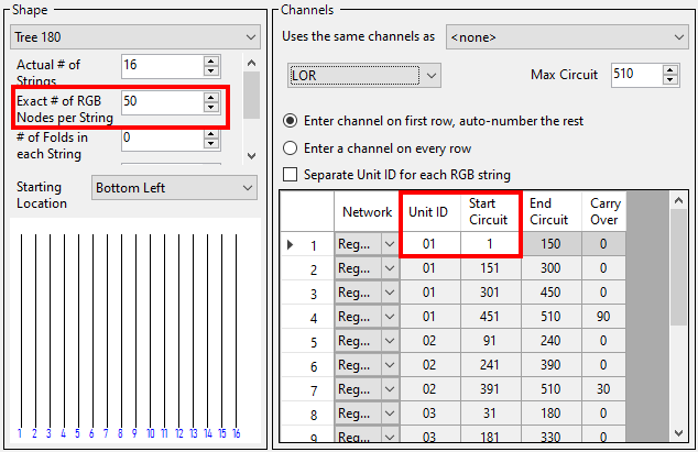
When using LOR mode and Advanced is off, then you should set up your Prop Definition similar to the following picture:
•Prop Definition's "Nodes per String" should match the PixCon16 Configuration "Pixels Per Output".
•Prop Definition's device type should be set to "LOR".
•Prop Definition's Unit Id and Start Circuit should match the corresponding PixCon16 Configuration.
•Prop Definition's "Max Circuit" should be set to 510.
•Prop Definition's "Enter channel on first row, auto-number the rest" should be selected.
•Prop Definition's "Separate Unit Id for each RGB string" should be unchecked.
Advanced - ON
There are 2 modes available for setting up the pixel ports of a PixCon16, simple and advanced. For most users, simple mode is all that will be needed. For more complex configuration options, please use the advanced mode.
Here you can set:
•an individual start universe and channel for each string
•the number of pixels attached to each port
•the number of "null pixels". Null pixels allow the controller to ignore or skip a specified number of pixels at the beginning of an output. This is useful when you want to extend the distance between controller and your actual lights, as the data signals used by pixel chips are not designed to travel over long distances. Sometimes the signal between controller and first pixel gets degraded and causes problems such as flickering lights. In these cases inserting a “fake” (null) pixel between controller and first real pixel can help as they reproduce the signal on their output; remember that they will not actually light up as they are ignored by the controller. The PixCon16 treats null pixels as an entirely different parameter to normal pixels. So for example if you had 50 pixels in your pixel fixture and needed to insert 2 null pixels before the start, the ‘Null Pixels’ field for that output would need to be set to 2 and the ‘Num Pixels’ field would remain at 50 (even though there are 52 physical pixels in total on that output).
•Use of the Zig-Zig feature is not recommended. Instead, use one of the matrix shapes in Prop Definition and set the number of folds.
•Grouping allows the user to specify how many physical pixels are grouped together and treated as one single pixel to the outside world. For example, if you had a pixel strip with 150 physical pixels on an output and entered 10 in the grouping field for that output, it would effectively turn that strip of 150 individual pixels into a strip of 15 individual ‘pixels’. Each ‘pixel’ would now actually consist of a group of 10 physical pixels all grouped together as one single ‘pixel’ as far as your lighting control software or console is concerned.
•Intensity Limit allows the user to specify a value between 0 and 100% for the brightness level of the pixels on a given output. Note that the brightness output is scaled based on the input level provided to the controller. This is used in circumstances where the lights are too bright for your application. If you set the Intensity limit to 50% for example, the PixCon16 would halve all incoming data values. Reducing brightness also reduces the amount of power consumed by the pixel strings.
•Turning on the reversed option tells the controller to light up the pixels in reverse order to the way that they are physically connected. This means the first pixel to light will actually be the last physical pixel on that output instead of the first physical pixel. Usually, it is best to leave this setting disabled, as it is easier to take care of such situations in your Preview.

The Control Tab - Advanced
LEDs Tab

The LEDs Tab
Pixel IC
Select your pixel string's chip-set here. The PixCon16 can support a variety of pixel driver chips -- which chips are supported depends on the firmware loaded to the board. Current Light-O-Rama pixel strings use the WS2811 chip (IC). This setting applies to all 16 outputs.
If in doubt, check the packaging:
![]()
Speed
Some pixel chip-sets have a low and high speed. If your chip-set supports high speed (current LOR pixel strings do), check the "Fast" box.
Controller Outputs
In most cases, select "Normal" here.
If using a controller that supports expanded mode and you select a pixel type that is a single wire protocol with no clock line (like WS2811), then you will have the option to select expanded mode. This mode allows the clock output on each of the pixel outputs on the control board to function as a data output instead of a clock line. This doubles the number of physical data outputs available and also increases the refresh rate. On a PixCon16 Mk2 for example, your data outputs will go from 16 to 32 in expanded mode and the max RGB pixels per data output will drop from 1020 to 510. In this mode, special care will be required in wiring your pixels to the connectors on the board.
LED Type
Some pixel drivers can operate RGB or RGBW LEDs. In this case, an option will be shown to select the type you are using. RGB LEDs use 3 channels and RGBW LEDs use 4 channels per pixel.
RGB Order
Under this tab you can also change the RGB (W) color order of all the outputs simultaneously, or change it for individual outputs separately. This is useful if the lights you are using are not physically wired in the standard red, green, blue order. To change the order of all outputs at once simply select the order from the drop-down box. To change specific outputs, click the ‘Advanced’ checkbox and then click the "Advanced" button to bring up the RGB (W) configuration window for individual outputs.
You can also set color order in Prop Definition. If your pixel strings are naturally in RGB order, then both the controller and Prop Definition should be set to RGB order. If not, set one to RGB and the other to the pixel string order. Things become very confusing if you try to change it both places!
Color Correction (Gamma)
These sliders allow you to adjust the relative amount of power supplied to each channel of a triplet attached to the 16 pixel ports of the board. Color Correction is typically used so that pixels attached to this board can be adjusted to more closely match pixels on other boards. Please note that this setting is for the entire board and not per port. Use the sliders to increase or decrease the amount of 'color' for each component.
Test Tab

The Test Tab
This tab allows you to remotely select a number of different hardware test modes on the controller that can help to determine if your pixels are connected correctly and are working as they should. Simply select the test you wish to run from the drop-down box to turn it on, and select either an individual pixel output or all pixel outputs for the test to be applied to. Note: Before running the tests the pixel type and outputs should be configured correctly or it will not work.
Misc Tab
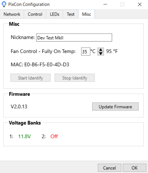
Nickname:
You should set the name of the board to something meaningful to you. For example, if this particular controller is used for a tree, you may want to name it 'Pixel Mega Tree' or the like.
Fan Control
Optionally, you can connect a fan to the PixCon16. When the board reaches the temperature specified here, the fan will be set to full on. If you don't have a fan connected, you can ignore this field. See the PixCon16 Hardware manual for more information.
Firmware Update:
To update the firmware, press the Update Firmware button. You will then be asked for the location of an LOR PixCon16 Firmware File. To ensure you have the latest firmware available, please check the Light-O-Rama website and download the latest available.
Once you have selected the correct file, the firmware update process will start. The process is typically safe to perform, however we recommend that you do not update firmware unless you are addressing a known problem, or need to add some new functionality that a new firmware offers.
When updating the firmware of a PixCon16, the power and status lights will flash on/off in different patterns. Do not power off the board while the update is in progress. If you are unsure if the update was applied properly or not, wait a few minutes and then observe the power and status lights. This will give the board enough time to reboot and stabilize. Also, pay attention to any instructions that may be shown on your screen.
Should the update process fail, the board could be in one of several states after the failure:
•If the status light is blinking and the power light is solid, this typically means the update was successful. However, it could also mean the board did not receive or it did not properly start the update process.
•If the power and status lights are alternating, then the board is currently in the boot-loader mode.
•If the power light is ON but the status light is OFF there was a problem with the firmware update.
In all cases after allowing the board to sit for a few minutes, power it off then back on. The board should return to normal operation at that time. If not, please refer to the hardware manual of the PixCon16 for additional troubleshooting information.