Introduction
The Light-O-Rama (LOR) Cosmic Color Pixies are low cost, high density RGB pixel controllers. They are available in 2, 4, 8 and 16 string versions. The maximum number of pixels on a string is 170 (340 with supporting firmware). They support a variety of RGB pixel controller ICs.
Unlike most multi-string pixel controllers, the Pixies do not require Ethernet. The Pixies run on a LOR network in either normal or enhanced mode at speeds up to and including 1Mbit/sec. An enhanced network is required to properly utilize these controllers. Enhanced mode allows for a much higher pixel change rate than a normal network. Pixies may also be used with Ethernet E1.31 or Art-Net by connecting them to a PixieLink adapter, providing an upgrade path as your show grows.
When used with 50-pixel strings, the Pixies can emulate the older Cosmic Color Ribbon (CCR) or Cosmic Color Bulb/Pixel (CCB/CCP) controllers. This means, for example, that a Pixie16D can look like 16 CCRs or 16 50-pixel CCB/CCP strings. The Pixie controllers support LOR effects as well as the macro and color effects extensions provided by the first generation CCR/CCB/CCP controllers.
The Windows Showtime software is used to design and build Sequences (controller commands that may be choreographed to audio/music.) These user created sequences and/or pre-programmed musical sequences available from LOR and other companies are then arranged into Shows. These shows are played by your PC or one of the LOR Show Directors.
Contents:
•Singing Character ‘Personalities’ (Choose Your Character)
•Connecting the Controller to a PC
•Connecting to a Show Director
•Connecting to another Controller
•Setting the DMX512 Start Address
•DMX Start Address DIP Switch Table
•LOR %intensity to DMX Intensities
The version of the Hardware Utility appears in the title bar to the right of “Light-O-Rama Hardware.” If the version number is less than 4.4.0, you will not be able to configure the Pixie controller. The latest version of the Showtime software from this location: www.lightorama.com ► Support ► Download Software. This is a full ShowTime Software download that includes the latest Hardware Utility.
Firmware Version
The initial firmware version was 1.01, unfortunately, controllers with this version have a bad bootloader. This means firmware upgrades are not possible. These boards must be returned to the factory to upgrade the bootloader. Version 1.02 is exactly the same as version 1.01 but has a working bootloader. This document reflects Pixie firmware version 1.07. The firmware version is determined by using the Refresh button in the Hardware Utility.
Pixel Type (RGB IC)
Each pixel on a ribbon or string has a digital RGB driver. These may be separate ICs, or they may be integrated with the RGB LEDs. These are called RGB ICs. See the Pixel Type (RGB Integrated Circuit) section for a list of supported RGB ICs.
Pixel Strings
Pixel strings/ribbons compatible with these controllers are available from Light-O-Rama and other vendors. Strings can be 5vdc or 12vdc (Pixie2 requires 12vdc strings). All strings on the controller must use the same RGB IC. Generally, 5vdc strings are usually limited to 50 pixels because of voltage drop due to the current draw. 12vdc pixel strings are good for 100 pixels. Low power 12vdc pixels are good to 150 per string.
Important Considerations
When powered by 5vdc, the Pixie controllers cannot supply the voltage (9vdc) required by most LOR accessories.
LOR effects (fading, twinkling, shimmer) done by the controller require a lot of memory. The Pixie16D can perform these effects on the first 50 pixels of each string, the Pixie8D on 100, and the Pixie2D and Pixie4D on 170. If you are running the network in Enhanced mode, these effects will be done by the Show Director or PC, so the memory limitation does not apply, and LOR effects are available on 170 pixel strings for all controllers.
We recommend leaving the top-most jumper off when configuring the RJ45 network jack wiring for LOR network mode. This disables accessory power to the network jacks. There have been problems with incorrectly user-made cables which swap wires and short out the accessory power supplies. This becomes a problem with multiple controllers as significant current may be available.
First vs. Second Generation Boards
First generation Pixies do not have Unit ID DIP switches and do not have reverse power protection circuitry. Reverse power protection only protects the controller; it does not protect the pixel strings.
For WS2811 (800KHz) and WS2801 pixels, the output networks on the pixel ports of first-generation boards allow up to 40’ between the controller and the first pixel. This is increased to 80’ for second generation boards. You may need to run heavier wire (18 gauge) to prevent voltage drop on the power leads to the first pixel, especially for 5v pixels. Voltage drop usually manifests itself as pixels appearing pink when white at full power is chosen.
There are three network protocols currently in use: LOR Normal, LOR Enhanced, and PixieLink.
LOR normal is the protocol that has been used by LOR controllers from year 0. It is the only way to access the CCR/CCB/CCP compatibility mode resolution, color effects and macros channels.
LOR Enhanced protocol is a newer compressed data protocol designed specifically for high density pixel displays. It is pretty much required for even a moderately active display.
PixieLink protocol is used between a PixieLink E1.31/Art-Net adapter and Pixies. The PixieLink adapter allows Pixies and other LOR G3 controllers to be used with a standard Ethernet E1.31 source.
The Pixie controllers understand all protocols and automatically detect network speeds from 19.2Kbits per second up to 17Mbps. All delivered Pixies have at least 5Mbps comm chips and will always work with PixieLink at 4.25Mbps. They will usually work with PixieLink at 8.5Mbps. The 8-pin socketed chip near the RJ45 jack may need to be upgraded to a 10Mbps chip to use the 17Mbps PixieLink speed.
In general, users don’t have to concern themselves with the network protocol unless they are running old devices. Some older devices will not understand Enhanced Protocol. Users will have to concern themselves with network speeds. At this time, only the PixCon and the Pixie controllers can handle 1Mbps Enhanced LOR, and only Pixies understand PixieLink protocol (4.25, 8.5, and 17Mbps).
The type of network (normal/enhanced) is selected in the Light-O-Rama Control Panel under the Networks tab.
Using the PixieLink adapter requires configuration of each pixel string (Unit ID) as a DMX universe. When the pixel strings are defined in the Sequence Editor, each one will have to be assigned a DMX universe number. These DMX universes will be assigned to Ethernet address(es) in Network Preferences under the DMX tab.
Assigning a Unit ID
Second generation Pixies have a DIP switch with 8 positions. This is used to set the unit ID. If all DIP switches are set to ‘off’, then the unit ID as set by the Hardware Utility will be used (see below). Refer to the LOR Unit ID DIP Switch Table for the mapping of your desired LOR address to DIP switch settings.
First generation Pixies do not have unit ID switches, so the Unit ID must be assigned with the Hardware Utility as follows:
If you have not installed the Light O Rama Windows Showtime Software, do it now. The controller must be powered by a 5-12vdc power supply . You can use one of LOR’s USB RS485 adapters. See the Connecting the Pixie to a PC section for more information.
Power up the controller. The Status LED will blink about twice/second. This means that the controller has booted and is waiting for the PC to talk to it.
Start the Hardware Utility – click start ► Light-O-Rama ► Light-O-Rama Control Panel. Select the Controller Setup tab and then Hardware Utility. You will see this window:
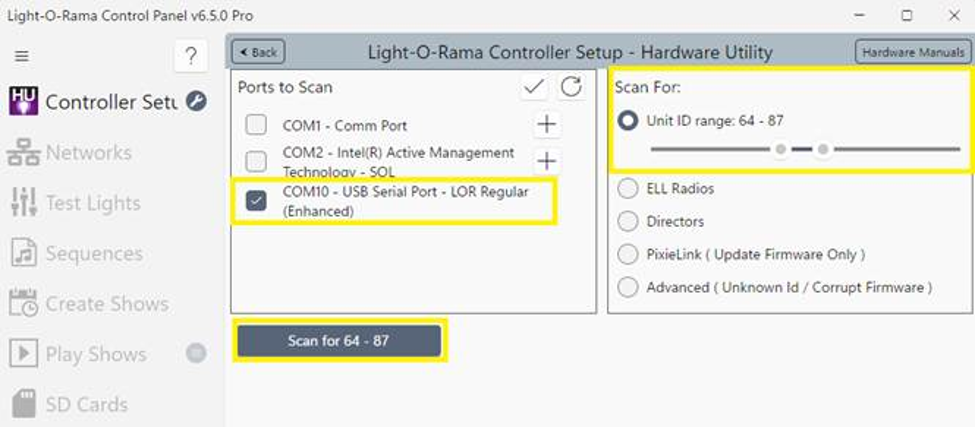
Select the COM port that matches your USB RS485 adapter. Scanning the full range from 01 – F0 can be time consuming. Consider adjusting the Scan For slider to a range that includes your controller’s current Unit IDs. Click the Scan for button to start the network scan. If more than one controller is found, disconnect other controllers and click the “Rescan” button. When assigning a unit ID, only one controller should be plugged into the USB RS485 adapter on the PC.
Steps to set/change unit ID:
Pixie Controllers may support Unit ID assignments in two ways. Physical DIP switches on the controller board or by using the Light-O-Rama Control Panel Hardware Utility. Light-O-Rama recommends using physical DIP switches to assign the Unit ID. Doing so can result in a computer-less experience. Some scenarios may require Unit ID configuration using the Light-O-Rama Control Panel Hardware Utility. If using the Hardware Utility for Unit ID configuration, and if you have a second-generation Pixie, the DIP switches must be set to 0 for the Unit ID to be set. ALL DIP switches must be in the OFF position.
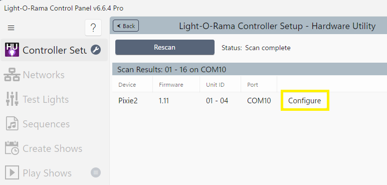
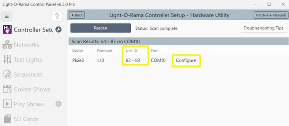
1. After scanning is complete, click "Configure" button.
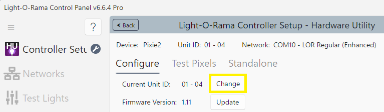
2. In the Current Unit ID section, click the “Change” button.
3. Use the New Starting Unit ID drop down menu to select the Unit ID you want.
4. Click the Change button to set your Pixie controller’s base unit ID. You will see a Unit ID Changed box – click OK
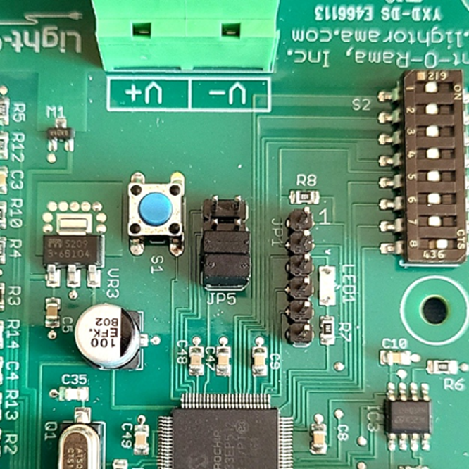
Your Pixie controller may have come with jumper(s) installed on JP5. These jumpers force a configuration that supports the type, color order and number of pixels you purchased with the Pixie controller. These jumpers will supersede those parameters settable by the Hardware Utility. Jumper 1 is nearest the JP5 labeled end.
Jumper What it does
J1 WS2811, 800 Khz, BRG, 50 pixels
J2 WS2801, RGB, 50 pixels
J3 WS2811, 800 Khz, RGB, 100 pixels
J4 V1 Singing Faces
J1 and J2 WS2811, 800 Khz, RGB, 340 pixels
The Hardware Utility is used to set the power-up configuration of the controller. Of the parameters configured below, only the Logical Resolution/Flip-status can be changed on-the-fly in sequences, and only in CCR compatibility mode. All other parameters are set by and can only be changed by the Hardware Utility.
Pixel Type (RGB Integrated Circuit)
After using the Hardware Utility to scan a controller, click the “Configure” button and then the “Advanced” button to update port/pixel type configurations. Remember to click the “Update Config” button to save changes to the controller. Note that a Pixie controller will have multiple Unit IDs displayed as a range. The first number of the Pixie Unit IDs range corresponds to the configured Unit ID of the controller. A two port controller would use two Unit IDs, one for each port. If pixels per port are configured greater than 170, each physical pixel port would use two Unit IDs (firmware supporting more than 170 pixels per port required).
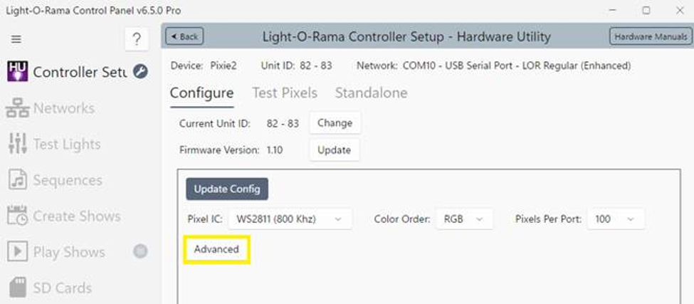
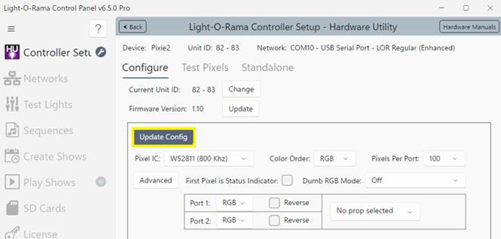
This field selects the type of pixel control integrated circuit. The currently supported pixel drivers are:
1.WS2811 400KHz
2.WS2811 800KHz
3.WS2801
4.SM16716
5.LPD6803 (LPD1101, D705A)
6.TMI1803 (UCS1903 400KHz)
7.TMI1804
8.TMI1809
9.DMX (Used by Pixie4DMX)*
10. 943
11. 943-2**
12. GS8208 800KHz (WS2813)
13. APA102 (SK9822)
14. UCS1903 800KHz (WS2811)
There are also some “(Reserved IC x), …” slots. These are so additional RGB ICs can be added without requiring a software release.
* This type outputs intensity data in DMX512 format. Only the Pixie4DMX has RS485 outputs which will create DMX512 universes that can be connected to DMX512 fixtures. Other Pixies will accept this output type, but will still output 5v logic levels, not RS485.
** If an RGB IC type is followed by “-n” it means that ‘n’ adjacent pixels will be combined by the controller. E.g. if the ribbons have 100 pixels, the controller is configured for 50 pixels and the RGB IC is 943-2, then 2 adjacent pixels on the ribbon will react for each of the 50 configured pixels. It reduces the number of pixels the ribbons appear to be by a factor of 2.
Selects the order in which the red, green, and blue intensities are sent to the RGB ICs. If you do not know the color order of your pixels, choose RGB. Then press the test button. The test pattern always starts with red, then green, and finally blue. The actual order of colors you see is what you need to set the color order to.
This sets the number of physical pixels on a port. Range is 1 to 170. If pixels per port are configured greater than 170, each physical pixel port would use two Unit IDs (firmware supporting more than 170 pixels per port required).
If the number of Pixels Per Port is not 50, then the only resolutions possible are 1 (pixel strings react as one big pixel), and full resolution – the pixels per port (logical resolution should be set to 50).
Otherwise, old CCR compatibility mode is possible, and the following applies:
Logical resolution is the number of pixels that a bulb string appears as in the Sequence Editor. This must be set to 50 if you intend to use the Resolution, Macro & Color Effect channels (old CCR/CCB/CCP compatibility). You can always change the logical resolution on the fly using the Resolution channel.
A bulb string has 50 physical pixels (bulbs,) but to make programming less tedious, it can be set to a lower logical resolution. This means that adjacent physical pixels (bulbs) will be merged. E.g. If the string is set to a logical resolution of 5 pixels, then 10 adjacent bulbs will respond as one – the string will appear to be 5 segments.
Note: The resolution, color effect and macro channels are only active for strings with 50 pixels in LOR network mode.
The first pixel is the one nearest the controller. Checking the “Reverse” box reverses this, making this making the pixel furthest from the controller the first pixel.
First Pixel is Status Indicator
If this box is checked, the status LED will be mirrored in white on the stringon string one’s pixel nearest the controller. This occurs for 60 seconds after power up. This check box exists to save the effort of having to open up the controller box up; you can just unplug and plug in the controller to check its status.
Checking this box causes a Pixie controller with smart strings to behave like a CMB16D or CMB24D with dumb strings. The first Unit ID of the Pixie2/4/8 will have 2/4/8 pixels which control the strings. A Pixie16 will use the first eight pixels of the first and second Unit IDs, so it will look like two CMB16D or CMB24D controllers. This feature exists because it is becoming impossible to purchase dumb RGB ribbons/pixels. This allows a Pixie to be a plug-in replacement in your sequences for CMB controllers.
This selects the speed at which an internal stand-alone sequence is run. 8 runs the sequence with 1 second of sequence commands equaling one actual second. Use this option to fine tune the speed of the stand-alone sequence.
DMX512 Input to Pixie2D & Pixie4D only
Set Pixie2 to 50 or 100 pixels/string. Set Pixie4 to 50 pixels/string. There is only one DMX mode:
DMX addresses Pixie2 Pixie4
1-150 1st string 50 pixels 50 pixels
151-300 2nd string 50 Pixels 50 pixels
151-450 2nd string 100 pixels n/a
301-450 3rd string n/a 50 pixels
The RJ45 jacks on the Pixie2D have jumpers to allow for LOR or DMX (E1.27-2) network wiring. If the DMX device driving the Pixie controller has an XLR 3-pin connector, you will need the LOR RJ-45 to XLR 3-pin Male connector. It is available from the Web Store on the accessories page:
www.lightorama.com/ ► LOR Store ► Accessories ► RJ-45 to XLR 3-pin Male (this adapter converts to LOR network wiring, not DMX E1.27-2 wiring.
This is the order in which the pixel channels appear in the Sequence Editor. The number of channels depends upon the configured pixels per port when not in CCR compatibility mode, and the resolution when in compatibility mode.
Triples means the channels will appear as R (channel 1) G (channel 2), B (channel 3) for the first pixel (the pixel nearest the controller,) then R (4), G
(5), B (6) for the next pixel, etc.
Sequential means that all the Rs (channel 1, 2, 3, …) will come first, then all the Gs and finally all the Bs. Sequential channel mode is only available on normal LOR networks, it does not work with Enhanced or PixieLink networks.
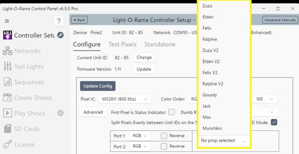
These drop down options are used to select one of the LOR props (singing trees). A prop is two adjacent 100-pixel strings. The controller understands the arrangement of the pixels so that the user does not have to individually program the pixels to manipulate the prop. This allows for sequences to be written that will work with any of the singing trees. Selecting a ‘prop’ reduces the number of pixels to the first 8 pixels on the first pixel string of the prop. Here is the pixel assignment:
Pixel 1 – Outline of the tree
Pixel 2 – Tree topper
Pixel 3 – Eyes closed
Pixel 4 – Eyes open
Pixel 5 – Mouth closed
Pixel 6 – Mouth half open
Pixel 7 – Mouth full open
Pixel 8 – Mouth ‘oh’
Singing Character ‘Personalities’ (Choose Your Character)
For use with Singing Characters, Pixie Controllers must be specially configured in the LOR Control Panel. (This reduces your network usage from 200 pixels per character to 14 pixels per character.)
Singing face configuration can vary subject to the version of the prop being used. V1 singing faces have 4 mouth movements (Open, Half Open, Closed, and “OH”)and V2 singing faces have 10 mouth movements (“Ah”, Open, Closed, Half Open, “etc”, “FV”, “L”, “MBP”, “OU”, “WQ”).
Jumpers (V1 Mode - Trees Only) - Deluxe SD Cards
JP5 - place the jumper on position 4 to have a Singing Tree to operate in simple V1 4- Mouth Mode. Leave this jumper off for standard RGBPlus 10-Mouth operation.
If the jumper is removed and a sequence (like RGBPlus) contains effects for both a V1 4-mouth tree and a V2 10-mouth tree, the singing tree will follow the 10-mouth tree sequencing by default.
Controller ID Configuration (Choose a Singing Part)
Single Face Packages with Pixie2 controllers come preset to ID 30 by default (Main Male Singer) and will need to be changed if you want the character to sing a different part. A Pixie8 package comes preset to play the parts below in order connected down the pairs of Pixie ports. “Swap a Prop’ Package Pixie2 IDs must be set by the customer before use.
Unit ID Setting Defaults Used in Sequences
30 - Main/Duet Male Singer Elden Jack
32 - Duet Male Singer 2 / Backup Vocals Felix Gourdy
34 - Backup Vocals Ralphie Max
36 - Main/Duet Female Singer Zuzu Munchkin
Software Control
The Pixies appear in a LOR Network at the unit ID set by the DIP switches or Hardware Utility plus 1, 3, 7 or 15 additional sequential unit IDs. The first unit ID corresponds to the first string, the second unit ID corresponds to the second pixel string, …
A pixel string is configured in the Sequence Editor as up to 170 pixels.
If you configure the Pixie for 50 physical pixels, each string appears as 160 channels. The first 150 channels are the R, G, and B channels for the 50 physical pixels. These channels can be combined into Sequence Editor RGB channels cutting the 150 to 50. The next 10 channels are the resolution, macro, and color effect channels. These are for compatibility mode with the old CCR/CCB/CCP.
Hardware Description
The pictures in this section are not to relative scale.
The Pixie2D is only available in a weatherproof plastic box with a universal power supply.
The other Pixies are available as boards or in weatherproof boxes with a power supply.
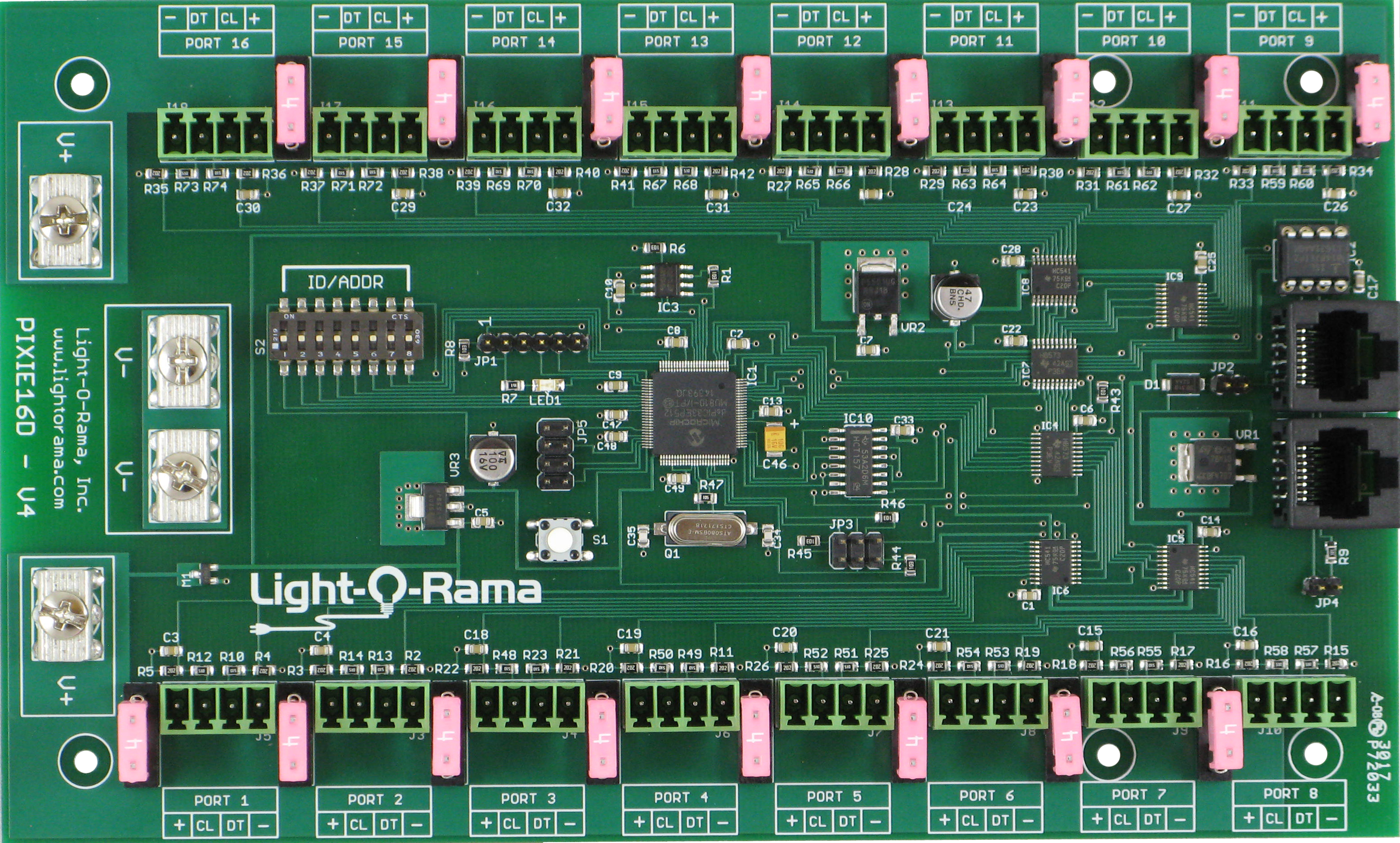
The labelling of the on-board jumpers (JP2-JP5) is not consistent across Pixies. Be sure to consult the following pictures and descriptions for your board.
The second-generation Pixie boards have protection from reverse polarity power connection. This only protects the board logic, not the connected pixel strings. Connect the board power before attaching pixel strings. If the status LED flashes, then the power is correctly connected, and you can connect your pixel strings.
Pixie2D (White plastic box, 12 VDC)
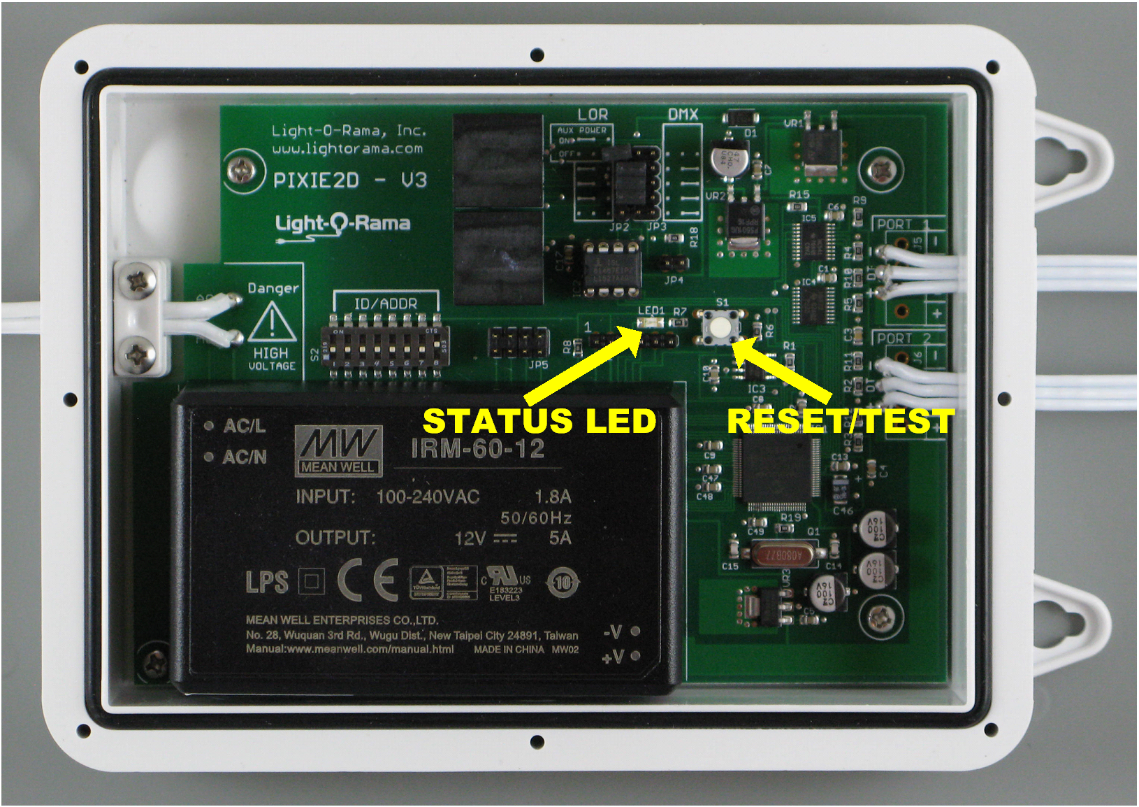
•JP2/JP3 jumpers select the network wiring on the RJ45 jacks (LOR or DMX). LOR network without accessory power enabled shown.
•JP4 install jumper to connect 120Ω termination resistor.
•JP5 is used to select some factory configurations and must be empty to allow Hardware Utility setting of RGB IC, pixels/string, and color order.
•DIP switches 1-8 select unit ID/DMX address unless they are all off; in which case the Hardware Utility is used to make the selection.
•The power supply is current limited, so no fuse on the pixel strings is required
•There is an AC power fuse in the AC plug.
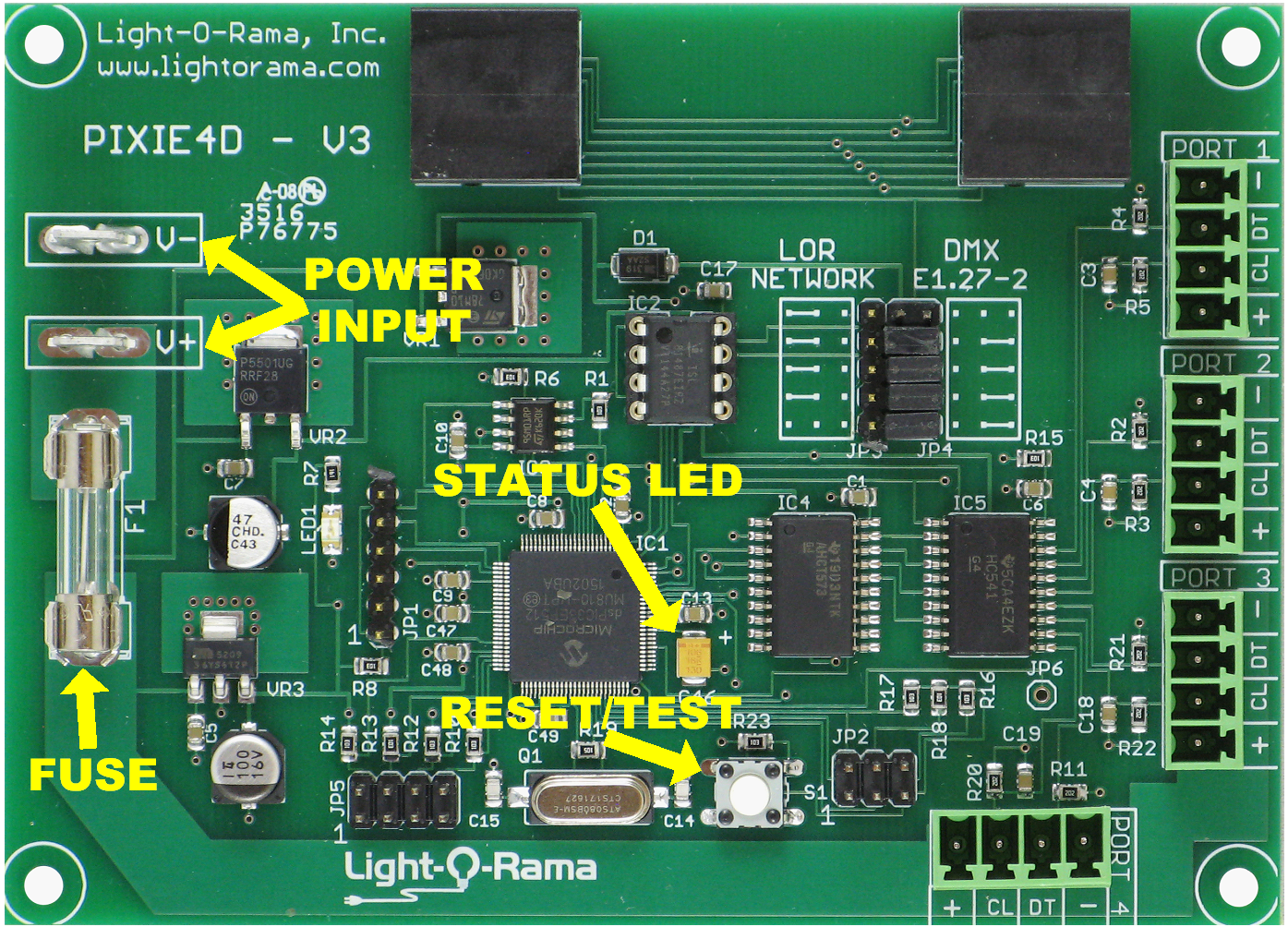
•JP2 is used to connect inputs (interactive show triggers) to the controller.
•JP3/JP4 jumpers select the network wiring on the RJ45 jacks (LOR or DMX). DMX network shown. It is recommended that you leave the top-most jumper off in LOR network mode. This will disable accessory power to the network jacks.
•JP5 is used to select some factory configurations and must be empty to allow Hardware Utility setting of RGB IC, pixels/string, and color order.
•The fuse limits current for all four strings.
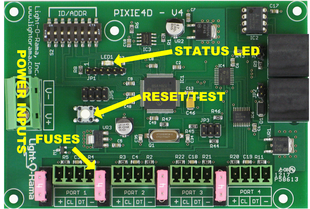
•JP2 install jumper to connect accessory power to RJ45 jacks.
•JP3 is used to connect inputs (interactive show triggers) to the controller.
•JP4 install jumper to connect 120Ω termination resistor.
•JP5 is used to select some factory configurations and must be empty to allow proper operation of the Pixie4DMX and to allow the Hardware Utility setting of pixels/string and color order.
•The fuses limit current for individual strings.
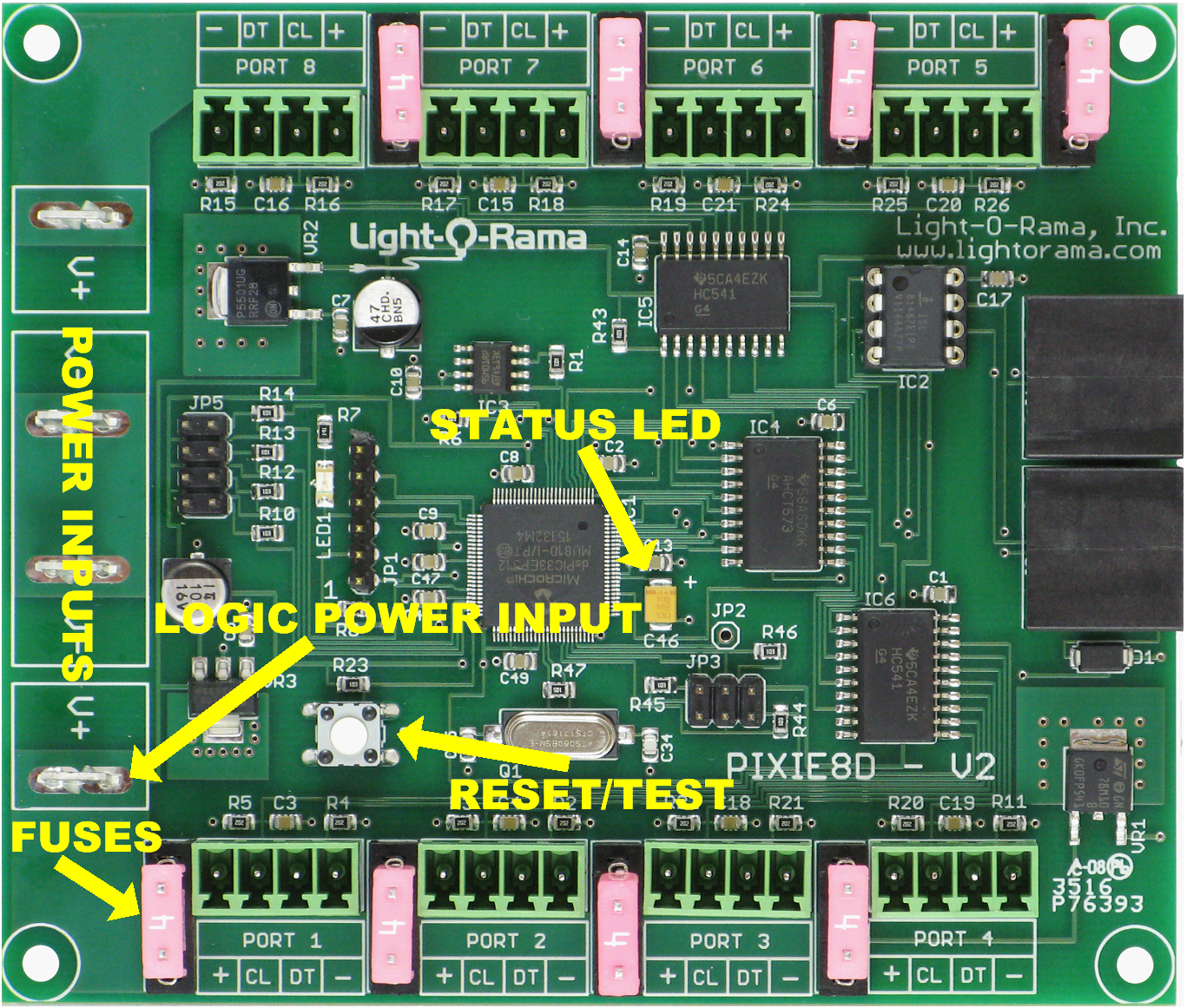
•JP3 is used to connect inputs (interactive show triggers) to the controller.
•JP5 is used to select some factory configurations and must be empty to allow the Hardware Utility setting of pixels/string and color order.
•The fuses limit current for individual strings.
•Power must be connected to the “Logic Power Input” side of the controller for operation.
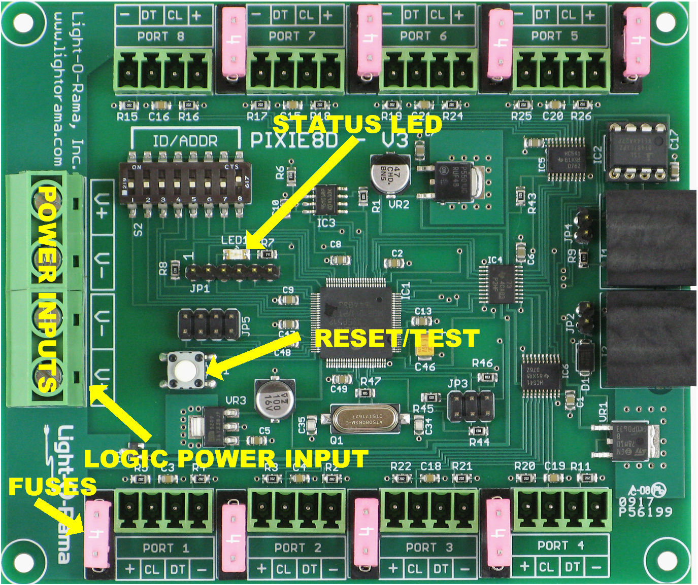
•JP2 install jumper to connect accessory power to RJ45 jacks.
•JP3 is used to connect inputs (interactive show triggers) to the controller.
•JP4 install jumper to connect 120Ω termination resistor.
•JP5 is used to select some factory configurations and must be empty to allow proper operation of the Pixie4DMX and to allow the Hardware Utility setting of pixels/string and color order.
•The fuses limit current for individual strings.
•Power must be connected to the “Logic Power Input” side of the controller for operation.
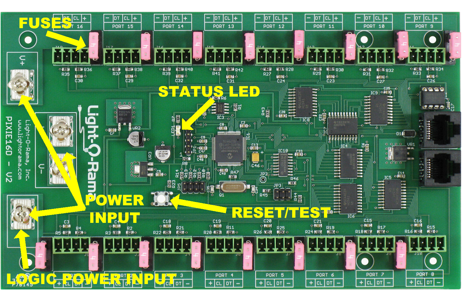
•JP3 is used to connect inputs (interactive show triggers) to the controller.
•JP5 is used to select some factory the Hardware Utility setting of RGB IC, pixels/string and color order.
•The fuses limit current for individual strings.
•Power must be connected to the “Logic Power Input” side of the controller for operation.
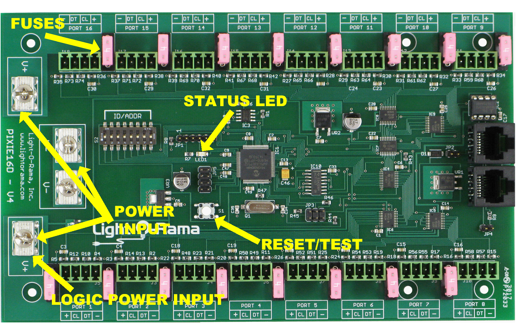
•JP2 install jumper to connect accessory power to RJ45 jacks.
•JP3 is used to connect inputs (interactive show triggers) to the controller.
•JP4 install jumper to connect 120Ω termination resistor.
•JP5 is used to select some factory the Hardware Utility setting of RGB IC, pixels/string and color order.
•The fuses limit current for individual strings.
•Power must be connected to the “Logic Power Input” side of the controller for operation.
Status LED
•Blinks twice per second if the controller has booted correctly but is not connected to an active network
•Solid on if the controller sees a network director – either a PC or Show Director
•Blinks one long on and a short off repeatedly if in the bootloader. This means that the firmware is not loaded or corrupted. See the Updating the Pixie Firmware section to load firmware
•Flashing rapidly indicates resetting because you are holding the reset button during power up or while the controller is up and running.
Input Header (JP2 or JP3)
The Input Header is used to provide interactive triggers for shows or to start a stand-alone sequence. It has 10vdc @ 300ma available for devices like motion detectors that might be used as triggers. The following diagram shows the connections on the header:
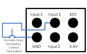
A 6-pin socket with a 2’ cable is available from LOR to simplify connections to the header.
Inputs 1 & 3 are for normally open switches. Input 2 is for a normally closed switch (security devices like motion sensors should use this input.)
Fuses
See the Hardware Description section pictures.
Jumpers (JP5)
These jumpers are used to force a configuration for the RGB IC, color order and pixels/string. If your board has a jumper, you can transfer the settings of this jumper into the configuration EEPROM by changing any parameter on the configuration page or by changing the unit ID. Once you have done this, you can remove the jumper and the Hardware Utility will be able to change any parameter.
See the section Setting the Configuration for a description of what the JP5 jumpers do.
Power Input(s)
These connectors are used to power the Pixies and the attached pixel strings/ribbons. The Pixie8 and the Pixie16 have two banks; one bank’s power connector is used to supply logic power. This power input must be powered for the Pixie to work. The Pixies work with 5vdc or 12vdc pixels.
Reset/Test Button
Press and hold this button when powering up the controller to reset it. When the status LED flashes quickly, the reset is complete. Release the button and the controller will reboot. Resetting the controller at power up clears any standalone sequence and tests the stand alone EEPROM. A rapid flash indicates that everything is good; otherwise an error code will be flashed.
Press this button momentarily after the controller has booted to run a simple test pattern on the pixel strings. The test will run until you momentarily press the button again or five minutes go by. The test pattern runs red, then green, and then blue down all pixel strings and repeats.
Press and hold this button after the controller has booted until the status LED flashes rapidly to clear the standalone sequence. Release the button when the status LED flashes rapidly.
The controller disconnects from the network during reset or when the test pattern is running.
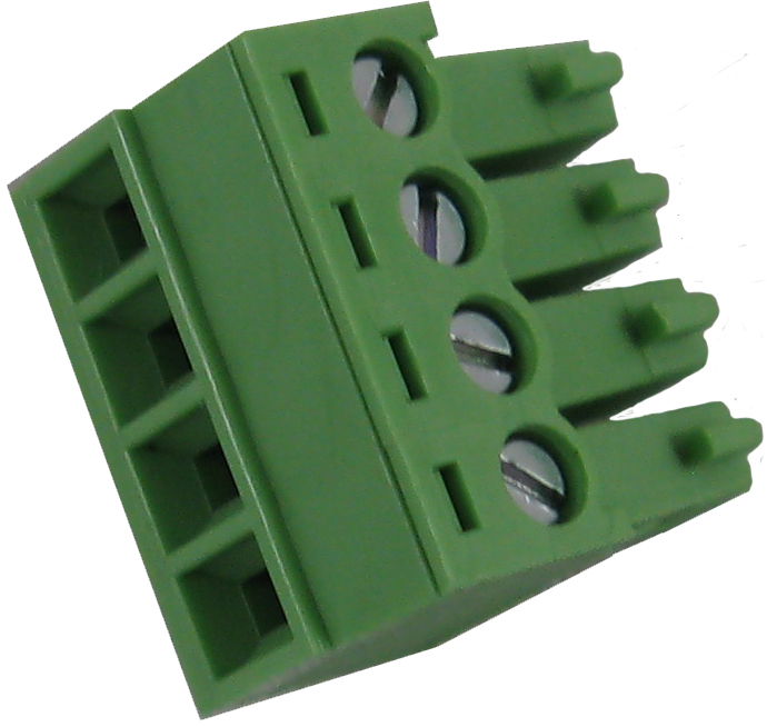
The string connector plugs used on the Pixie4D, Pixie8D and Pixie16D allow ribbons or pixel strings to be easily connected to the controller. Simply pull the plug out of the controller and use its screw terminals to attach the string. Use the legend on the controller to determine where ground, clock, data and power for the string go. The clock and data lines are always 5vdc logic levels. For three wire strings, connect the control wire to the data connection on the controller.
Network Jacks
Two RJ45 jacks used to daisy chain this controller into a LOR network. The Pixie2D and Pixie4D will also work in DMX512 Networks. The Pixie2 has jumpers to select DMX (E1.27-2) wiring or LOR network wiring.
Connecting the Controller to a PC
You will need the following to connect your controller to a PC:
•Showtime Windows Software
•USB RS485 Adapter
•CAT5 cable to connect USB485 to Light-O-Rama controller(s)
•Your controller
The first three items are available in the LOR SPK-ST Generic Starter Package. www.lightorama.com ► LOR Store ► Components. You will have to choose an RS485 adapter type. Choose the USB485 if you have no intention of going wireless from your PC to the controller. If wireless is desired, get the USB485B.
The following diagram shows how the pieces fit together:
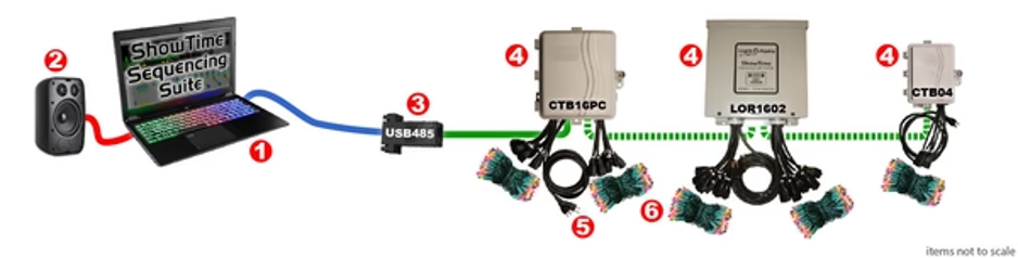
1.Your PC running the Showtime Windows Software
2.Your PC speakers to play the music
3.RS485 Adapter to convert short distance USB to long distance RS485
4.Light-O-Rama controllers Controller
5.Power Connector
6.Light strings
If your USB adapter has more than one jack, you can use either.
You can use either jack on the Pixie controller.
Connecting to a Show Director
You will need the following to connect your controller to a Show Director:
•LOR1602MP3 Show-in-a-Box controller (has an internal MP3 Show Director), MP3 Show DirectorCAT5 cable
•Your Pixie controller
•Possibly a 9 to 9 vdc power supply for the Show Directors. Required if the Pixie is being used at 5vdc.
You can use either of the larger jacks on the show director and either jack on the Pixie controller..
Connecting to another Controller
You can go from either large jack on one controller to either jack on the Pixie controller.
Updating the Pixie Firmware
You must have:
•Hardware Utility version 4.3.16 or later, see the section Hardware Utility Version
•The Pixie powered and connected to the PC via an RS485 adapter – Do not use wireless
Get the latest firmware. www.lightorama.com ► Support ► Firmware section. Click the Firmware button for the correct firmware (Pixie2D, Pixie4D, Pixie8D or Pixie16D) and save the firmware file on your PC. Note where on your PC you have saved the firmware file.
Start the LightORama Control Panel if it is not running by clicking start ► Light-O-Rama ► Light-O-Rama Control Panel.
Access the Hardware Utility by clicking on the Controller Setup tab and then selecting the Hardware utility. Select your COM port(s) to scan and click the “Scan” button. If more than one controller is found, it is recommended to disconnect them and scan again before updating firmware.
Click the “Configure” button next to the controller found during the scan. Next to the Firmware version, click the “Update” button.
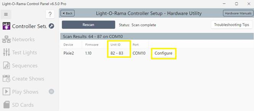
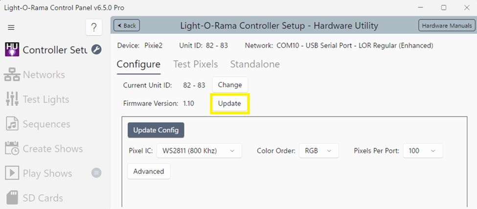
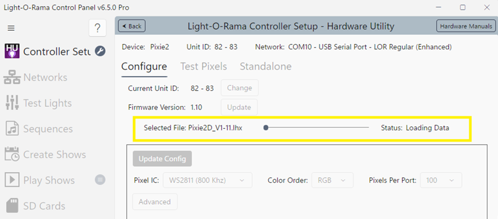
A window will open. Select the applicable firmware file. The firmware will start to load. During the firmware update, the window should look similar to the window below. The update progress bar will fill from left to right. Do not interrupt USB, network, or power connections during this loading process.
When the new firmware is loaded, the updated Firmware Version will be shown next to the “Update” button, and the Pixie controller will reboot.
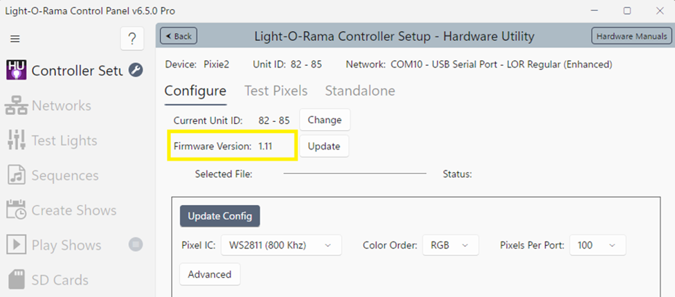
Newer firmware can allow up to 340 pixels per port. When the controller is configured with more than 170 pixels per port, each port will then use 2 Unit IDs. A Pixie16 with 16 physical ports would then use 32 Unit IDs, two IDs per port. Where a Pixie2 with 2 physical ports would use up to 4 Unit IDs.
Setting the DMX512 Start Address
The DMX starting address is selected using the DIP switches. DMX512 input mode is only possible with the Pixie2D & Pixie4D. Refer to the DMX Start Address DIP Switch Table section, or use the following computation:
The start address is selected by turning on DIP switches so the total adds up to the address you want. The maximum DMX start address is 255.
Switch 1 has a value of 128. Switch 2 has a value of 64. Switch 3=32, Switch 4=16, Switch 5=8, Switch 6=4.Switch 7=2, Switch 8=1.
For a DMX start address of 129, switches 1-8 would be set to 1000 0001 where 1 represents ON and 0 represents off.
LOR ID |
Switches 1-8 |
LOR ID |
Switches 1-8 |
LOR ID |
Switches 1-8 |
|||
01 |
0000 |
0001 |
29 |
0010 |
1001 |
51 |
0101 |
0001 |
02 |
0000 |
0010 |
2A |
0010 |
1010 |
52 |
0101 |
0010 |
03 |
0000 |
0011 |
2B |
0010 |
1011 |
53 |
0101 |
0011 |
04 |
0000 |
0100 |
2C |
0010 |
1100 |
54 |
0101 |
0100 |
05 |
0000 |
0101 |
2D |
0010 |
1101 |
55 |
0101 |
0101 |
06 |
0000 |
0110 |
2E |
0010 |
1110 |
56 |
0101 |
0110 |
07 |
0000 |
0111 |
2F |
0010 |
1111 |
57 |
0101 |
0111 |
08 |
0000 |
1000 |
30 |
0011 |
0000 |
58 |
0101 |
1000 |
09 |
0000 |
1001 |
31 |
0011 |
0001 |
59 |
0101 |
1001 |
0A |
0000 |
1010 |
32 |
0011 |
0010 |
5A |
0101 |
1010 |
0B |
0000 |
1011 |
33 |
0011 |
0011 |
5B |
0101 |
1011 |
0C |
0000 |
1100 |
34 |
0011 |
0100 |
5C |
0101 |
1100 |
0D |
0000 |
1101 |
35 |
0011 |
0101 |
5D |
0101 |
1101 |
0E |
0000 |
1110 |
36 |
0011 |
0110 |
5E |
0101 |
1110 |
0F |
0000 |
1111 |
37 |
0011 |
0111 |
5F |
0101 |
1111 |
10 |
0001 |
0000 |
38 |
0011 |
1000 |
60 |
0110 |
0000 |
11 |
0001 |
0001 |
39 |
0011 |
1001 |
61 |
0110 |
0001 |
12 |
0001 |
0010 |
3A |
0011 |
1010 |
62 |
0110 |
0010 |
13 |
0001 |
0011 |
3B |
0011 |
1011 |
63 |
0110 |
0011 |
14 |
0001 |
0100 |
3C |
0011 |
1100 |
64 |
0110 |
0100 |
15 |
0001 |
0101 |
3D |
0011 |
1101 |
65 |
0110 |
0101 |
16 |
0001 |
0110 |
3E |
0011 |
1110 |
66 |
0110 |
0110 |
17 |
0001 |
0111 |
3F |
0011 |
1111 |
67 |
0110 |
0111 |
18 |
0001 |
1000 |
40 |
0100 |
0000 |
68 |
0110 |
1000 |
19 |
0001 |
1001 |
41 |
0100 |
0001 |
69 |
0110 |
1001 |
1A |
0001 |
1010 |
42 |
0100 |
0010 |
6A |
0110 |
1010 |
1B |
0001 |
1011 |
43 |
0100 |
0011 |
6B |
0110 |
1011 |
1C |
0001 |
1100 |
44 |
0100 |
0100 |
6C |
0110 |
1100 |
1D |
0001 |
1101 |
45 |
0100 |
0101 |
6D |
0110 |
1101 |
1E |
0001 |
1110 |
46 |
0100 |
0110 |
6E |
0110 |
1110 |
1F |
0001 |
1111 |
47 |
0100 |
0111 |
6F |
0110 |
1111 |
20 |
0010 |
0000 |
48 |
0100 |
1000 |
70 |
0111 |
0000 |
21 |
0010 |
0001 |
49 |
0100 |
1001 |
71 |
0111 |
0001 |
22 |
0010 |
0010 |
4A |
0100 |
1010 |
72 |
0111 |
0010 |
23 |
0010 |
0011 |
4B |
0100 |
1011 |
73 |
0111 |
0011 |
24 |
0010 |
0100 |
4C |
0100 |
1100 |
74 |
0111 |
0100 |
25 |
0010 |
0101 |
4D |
0100 |
1101 |
75 |
0111 |
0101 |
26 |
0010 |
0110 |
4E |
0100 |
1110 |
76 |
0111 |
0110 |
27 |
0010 |
0111 |
4F |
0100 |
1111 |
77 |
0111 |
0111 |
28 |
0010 |
1000 |
50 |
0101 |
0000 |
78 |
0111 |
1000 |
LOR Unit ID DIP Switch Table cont’d
LOR ID |
Switches 1-8 |
LOR ID |
Switches 1-8 |
LOR ID |
Switches 1-8 |
|||
79 |
0111 |
1001 |
A1 |
1010 |
0001 |
C9 |
1100 |
1001 |
7A |
0111 |
1010 |
A2 |
1010 |
0010 |
CA |
1100 |
1010 |
7B |
0111 |
1011 |
A3 |
1010 |
0011 |
CB |
1100 |
1011 |
7C |
0111 |
1100 |
A4 |
1010 |
0100 |
CC |
1100 |
1100 |
7D |
0111 |
1101 |
A5 |
1010 |
0101 |
CD |
1100 |
1101 |
7E |
0111 |
1110 |
A6 |
1010 |
0110 |
CE |
1100 |
1110 |
7F |
0111 |
1111 |
A7 |
1010 |
0111 |
CF |
1100 |
1111 |
80 |
1000 |
0000 |
A8 |
1010 |
1000 |
D0 |
1101 |
0000 |
81 |
1000 |
0001 |
A9 |
1010 |
1001 |
D1 |
1101 |
0001 |
82 |
1000 |
0010 |
AA |
1010 |
1010 |
D2 |
1101 |
0010 |
83 |
1000 |
0011 |
AB |
1010 |
1011 |
D3 |
1101 |
0011 |
84 |
1000 |
0100 |
AC |
1010 |
1100 |
D4 |
1101 |
0100 |
85 |
1000 |
0101 |
AD |
1010 |
1101 |
D5 |
1101 |
0101 |
86 |
1000 |
0110 |
AE |
1010 |
1110 |
D6 |
1101 |
0110 |
87 |
1000 |
0111 |
AF |
1010 |
1111 |
D7 |
1101 |
0111 |
88 |
1000 |
1000 |
B0 |
1011 |
0000 |
D8 |
1101 |
1000 |
89 |
1000 |
1001 |
B1 |
1011 |
0001 |
D9 |
1101 |
1001 |
8A |
1000 |
1010 |
B2 |
1011 |
0010 |
DA |
1101 |
1010 |
8B |
1000 |
1011 |
B3 |
1011 |
0011 |
DB |
1101 |
1011 |
8C |
1000 |
1100 |
B4 |
1011 |
0100 |
DC |
1101 |
1100 |
8D |
1000 |
1101 |
B5 |
1011 |
0101 |
DD |
1101 |
1101 |
8E |
1000 |
1110 |
B6 |
1011 |
0110 |
DE |
1101 |
1110 |
8F |
1000 |
1111 |
B7 |
1011 |
0111 |
DF |
1101 |
1111 |
90 |
1001 |
0000 |
B8 |
1011 |
1000 |
E0 |
1110 |
0000 |
91 |
1001 |
0001 |
B9 |
1011 |
1001 |
E1 |
1110 |
0001 |
92 |
1001 |
0010 |
BA |
1011 |
1010 |
E2 |
1110 |
0010 |
93 |
1001 |
0011 |
BB |
1011 |
1011 |
E3 |
1110 |
0011 |
94 |
1001 |
0100 |
BC |
1011 |
1100 |
E4 |
1110 |
0100 |
95 |
1001 |
0101 |
BD |
1011 |
1101 |
E5 |
1110 |
0101 |
96 |
1001 |
0110 |
BE |
1011 |
1110 |
E6 |
1110 |
0110 |
97 |
1001 |
0111 |
BF |
1011 |
1111 |
E7 |
1110 |
0111 |
98 |
1001 |
1000 |
C0 |
1100 |
0000 |
E8 |
1110 |
1000 |
99 |
1001 |
1001 |
C1 |
1100 |
0001 |
E9 |
1110 |
1001 |
9A |
1001 |
1010 |
C2 |
1100 |
0010 |
EA |
1110 |
1010 |
9B |
1001 |
1011 |
C3 |
1100 |
0011 |
EB |
1110 |
1011 |
9C |
1001 |
1100 |
C4 |
1100 |
0100 |
EC |
1110 |
1100 |
9D |
1001 |
1101 |
C5 |
1100 |
0101 |
ED |
1110 |
1101 |
9E |
1001 |
1110 |
C6 |
1100 |
0110 |
EE |
1110 |
1110 |
9F |
1001 |
1111 |
C7 |
1100 |
0111 |
EF |
1110 |
1111 |
A0 |
1010 |
0000 |
C8 |
1100 |
1000 |
F0 |
1111 |
0000 |
DMX Start Address DIP Switch Table
Start |
Switches 1-8 |
Start |
Switches 1-8 |
Start |
Switches 1-8 |
|||
1 |
0000 |
0001 |
41 |
0010 |
1001 |
81 |
0101 |
0001 |
2 |
0000 |
0010 |
42 |
0010 |
1010 |
82 |
0101 |
0010 |
3 |
0000 |
0011 |
43 |
0010 |
1011 |
83 |
0101 |
0011 |
4 |
0000 |
0100 |
44 |
0010 |
1100 |
84 |
0101 |
0100 |
5 |
0000 |
0101 |
45 |
0010 |
1101 |
85 |
0101 |
0101 |
6 |
0000 |
0110 |
46 |
0010 |
1110 |
86 |
0101 |
0110 |
7 |
0000 |
0111 |
47 |
0010 |
1111 |
87 |
0101 |
0111 |
8 |
0000 |
1000 |
48 |
0011 |
0000 |
88 |
0101 |
1000 |
9 |
0000 |
1001 |
49 |
0011 |
0001 |
89 |
0101 |
1001 |
10 |
0000 |
1010 |
50 |
0011 |
0010 |
90 |
0101 |
1010 |
11 |
0000 |
1011 |
51 |
0011 |
0011 |
91 |
0101 |
1011 |
12 |
0000 |
1100 |
52 |
0011 |
0100 |
92 |
0101 |
1100 |
13 |
0000 |
1101 |
53 |
0011 |
0101 |
93 |
0101 |
1101 |
14 |
0000 |
1110 |
54 |
0011 |
0110 |
94 |
0101 |
1110 |
15 |
0000 |
1111 |
55 |
0011 |
0111 |
95 |
0101 |
1111 |
16 |
0001 |
0000 |
56 |
0011 |
1000 |
96 |
0110 |
0000 |
17 |
0001 |
0001 |
57 |
0011 |
1001 |
97 |
0110 |
0001 |
18 |
0001 |
0010 |
58 |
0011 |
1010 |
98 |
0110 |
0010 |
19 |
0001 |
0011 |
59 |
0011 |
1011 |
99 |
0110 |
0011 |
20 |
0001 |
0100 |
60 |
0011 |
1100 |
100 |
0110 |
0100 |
21 |
0001 |
0101 |
61 |
0011 |
1101 |
101 |
0110 |
0101 |
22 |
0001 |
0110 |
62 |
0011 |
1110 |
102 |
0110 |
0110 |
23 |
0001 |
0111 |
63 |
0011 |
1111 |
103 |
0110 |
0111 |
24 |
0001 |
1000 |
64 |
0100 |
0000 |
104 |
0110 |
1000 |
25 |
0001 |
1001 |
65 |
0100 |
0001 |
105 |
0110 |
1001 |
26 |
0001 |
1010 |
66 |
0100 |
0010 |
106 |
0110 |
1010 |
27 |
0001 |
1011 |
67 |
0100 |
0011 |
107 |
0110 |
1011 |
28 |
0001 |
1100 |
68 |
0100 |
0100 |
108 |
0110 |
1100 |
29 |
0001 |
1101 |
69 |
0100 |
0101 |
109 |
0110 |
1101 |
30 |
0001 |
1110 |
70 |
0100 |
0110 |
110 |
0110 |
1110 |
31 |
0001 |
1111 |
71 |
0100 |
0111 |
111 |
0110 |
1111 |
32 |
0010 |
0000 |
72 |
0100 |
1000 |
112 |
0111 |
0000 |
33 |
0010 |
0001 |
73 |
0100 |
1001 |
113 |
0111 |
0001 |
34 |
0010 |
0010 |
74 |
0100 |
1010 |
114 |
0111 |
0010 |
35 |
0010 |
0011 |
75 |
0100 |
1011 |
115 |
0111 |
0011 |
36 |
0010 |
0100 |
76 |
0100 |
1100 |
116 |
0111 |
0100 |
37 |
0010 |
0101 |
77 |
0100 |
1101 |
117 |
0111 |
0101 |
38 |
0010 |
0110 |
78 |
0100 |
1110 |
118 |
0111 |
0110 |
39 |
0010 |
0111 |
79 |
0100 |
1111 |
119 |
0111 |
0111 |
40 |
0010 |
1000 |
80 |
0101 |
0000 |
120 |
0111 |
1000 |
DMX Start Address DIP Switch Table cont’d
Start |
Switches 1-8 |
Start |
Switches 1-8 |
Start |
Switches 1-8 |
|||
121 |
0111 |
1001 |
161 |
1010 |
0001 |
201 |
1100 |
1001 |
122 |
0111 |
1010 |
162 |
1010 |
0010 |
202 |
1100 |
1010 |
123 |
0111 |
1011 |
163 |
1010 |
0011 |
203 |
1100 |
1011 |
124 |
0111 |
1100 |
164 |
1010 |
0100 |
204 |
1100 |
1100 |
125 |
0111 |
1101 |
165 |
1010 |
0101 |
205 |
1100 |
1101 |
126 |
0111 |
1110 |
166 |
1010 |
0110 |
206 |
1100 |
1110 |
127 |
0111 |
1111 |
167 |
1010 |
0111 |
207 |
1100 |
1111 |
128 |
1000 |
0000 |
168 |
1010 |
1000 |
208 |
1101 |
0000 |
129 |
1000 |
0001 |
169 |
1010 |
1001 |
209 |
1101 |
0001 |
130 |
1000 |
0010 |
170 |
1010 |
1010 |
210 |
1101 |
0010 |
131 |
1000 |
0011 |
171 |
1010 |
1011 |
211 |
1101 |
0011 |
132 |
1000 |
0100 |
172 |
1010 |
1100 |
212 |
1101 |
0100 |
133 |
1000 |
0101 |
173 |
1010 |
1101 |
213 |
1101 |
0101 |
134 |
1000 |
0110 |
174 |
1010 |
1110 |
214 |
1101 |
0110 |
135 |
1000 |
0111 |
175 |
1010 |
1111 |
215 |
1101 |
0111 |
136 |
1000 |
1000 |
176 |
1011 |
0000 |
216 |
1101 |
1000 |
137 |
1000 |
1001 |
177 |
1011 |
0001 |
217 |
1101 |
1001 |
138 |
1000 |
1010 |
178 |
1011 |
0010 |
218 |
1101 |
1010 |
139 |
1000 |
1011 |
179 |
1011 |
0011 |
219 |
1101 |
1011 |
140 |
1000 |
1100 |
180 |
1011 |
0100 |
220 |
1101 |
1100 |
141 |
1000 |
1101 |
181 |
1011 |
0101 |
221 |
1101 |
1101 |
142 |
1000 |
1110 |
182 |
1011 |
0110 |
222 |
1101 |
1110 |
143 |
1000 |
1111 |
183 |
1011 |
0111 |
223 |
1101 |
1111 |
144 |
1001 |
0000 |
184 |
1011 |
1000 |
224 |
1110 |
0000 |
145 |
1001 |
0001 |
185 |
1011 |
1001 |
225 |
1110 |
0001 |
146 |
1001 |
0010 |
186 |
1011 |
1010 |
226 |
1110 |
0010 |
147 |
1001 |
0011 |
187 |
1011 |
1011 |
227 |
1110 |
0011 |
148 |
1001 |
0100 |
188 |
1011 |
1100 |
228 |
1110 |
0100 |
149 |
1001 |
0101 |
189 |
1011 |
1101 |
229 |
1110 |
0101 |
150 |
1001 |
0110 |
190 |
1011 |
1110 |
230 |
1110 |
0110 |
151 |
1001 |
0111 |
191 |
1011 |
1111 |
231 |
1110 |
0111 |
152 |
1001 |
1000 |
192 |
1100 |
0000 |
232 |
1110 |
1000 |
153 |
1001 |
1001 |
193 |
1100 |
0001 |
233 |
1110 |
1001 |
154 |
1001 |
1010 |
194 |
1100 |
0010 |
234 |
1110 |
1010 |
155 |
1001 |
1011 |
195 |
1100 |
0011 |
235 |
1110 |
1011 |
156 |
1001 |
1100 |
196 |
1100 |
0100 |
236 |
1110 |
1100 |
157 |
1001 |
1101 |
197 |
1100 |
0101 |
237 |
1110 |
1101 |
158 |
1001 |
1110 |
198 |
1100 |
0110 |
238 |
1110 |
1110 |
159 |
1001 |
1111 |
199 |
1100 |
0111 |
239 |
1110 |
1111 |
160 |
1010 |
0000 |
200 |
1100 |
1000 |
240 |
1111 |
0000 |
DMX Start Address DIP Switch Table cont’d
Start |
Switches 1-8 |
Start |
Switches 1-8 |
Start |
Switches 1-8 |
|||
241 |
0000 |
0001 |
246 |
0010 |
1001 |
251 |
0101 |
0001 |
242 |
0000 |
0010 |
247 |
0010 |
1010 |
252 |
0101 |
0010 |
243 |
0000 |
0011 |
248 |
0010 |
1011 |
253 |
0101 |
0011 |
244 |
0000 |
0100 |
249 |
0010 |
1100 |
254 |
0101 |
0100 |
245 |
0000 |
0101 |
250 |
0010 |
1101 |
255 |
0101 |
0101 |
LOR %intensity to DMX Intensities
LOR |
DMX |
LOR |
DMX |
LOR |
DMX |
0 |
0 |
34 |
86 |
68 |
173 |
1 |
2 |
35 |
89 |
69 |
175 |
2 |
5 |
36 |
91 |
70 |
178 |
3 |
7 |
37 |
94 |
71 |
181 |
4 |
10 |
38 |
96 |
72 |
183 |
5 |
12 |
39 |
99 |
73 |
186 |
6 |
15 |
40 |
102 |
74 |
188 |
7 |
17 |
41 |
104 |
75 |
191 |
8 |
20 |
42 |
107 |
76 |
193 |
9 |
22 |
43 |
109 |
77 |
196 |
10 |
25 |
44 |
112 |
78 |
198 |
11 |
28 |
45 |
114 |
79 |
201 |
12 |
30 |
46 |
117 |
80 |
204 |
13 |
33 |
47 |
119 |
81 |
206 |
14 |
35 |
48 |
122 |
82 |
209 |
15 |
38 |
49 |
124 |
83 |
211 |
16 |
40 |
50 |
127 |
84 |
214 |
17 |
43 |
51 |
130 |
85 |
216 |
18 |
45 |
52 |
132 |
86 |
219 |
19 |
48 |
53 |
135 |
87 |
221 |
20 |
51 |
54 |
137 |
88 |
224 |
21 |
53 |
55 |
140 |
89 |
226 |
22 |
56 |
56 |
142 |
90 |
229 |
23 |
58 |
57 |
145 |
91 |
232 |
24 |
61 |
58 |
147 |
92 |
234 |
25 |
63 |
59 |
150 |
93 |
237 |
26 |
66 |
60 |
153 |
94 |
239 |
27 |
68 |
61 |
155 |
95 |
242 |
28 |
71 |
62 |
158 |
96 |
244 |
29 |
73 |
63 |
160 |
97 |
247 |
30 |
76 |
64 |
163 |
98 |
249 |
31 |
79 |
65 |
165 |
99 |
252 |
32 |
81 |
66 |
168 |
100 |
255 |
33 |
84 |
67 |
170 |
|
|
Specifications
|
Pixie2D |
Pixie4D |
Pixie8D |
Pixie16D |
Strings |
2 |
4 |
8 |
16 |
Pixels per string |
340 |
340 |
340 |
340 |
Strings per bank |
n/a |
n/a |
4 |
8 |
Amps/bank |
n/a |
n/a |
16 |
32 |
Total Amps |
10* |
16 |
32 |
64 |
Voltage DC |
5-12* |
5-12 |
5-12 |
5-12 |
Max LOR Net Speed |
1Mbps |
1Mbps |
1Mbps |
1Mbps |
Operating Temp |
-30º F to 140º F |
-30º F to 140º F |
-30º F to 140º F |
-30º F to 140º F |
Dimensions |
6½”L x 4⅞”W x1⅞”H* |
4⅝L x 3⅜” W x 1”H |
4½”L x 3⅞”W x 1”H |
7⅞”L x 4¾”W x 1”H |
* The Pixie2 is currently only sold with a 5amp, 12vdc power supply in a weatherproof plastic box.
Circuit boards available for Pixie4, Pixie8 & Pixie16.
Pixie 4,8,16 available in a plastic box with power supply.