Introduction
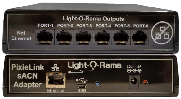
The Light-O-Rama (LOR) PixieLink sACN adapter converts standard E1.31 (streaming ACN) or Art-Net into six RS485 output networks. Each output network can be configured as a DMX universe, an Enhanced LOR network, or a PixieLink protocol network. The output port protocol (DMX, ELOR, PixieLink) is individually configurable for each port.
The PixieLink adapter receives sACN or Art-Net over a standard 10/100 Mbps LAN. It will process broadcast messages, and/or messages to its specific IP address.
When a port on the PixieLink adapter is configured as a DMX universe, the adapter will pick the first configured universe out of the LAN traffic and output it as a DMX512 RS485 network.
LOR Pixie controllers use one unit ID for each string of pixels on the controller. E.g. for a Pixie2 with an assigned unit ID of 03, the first pixel string on the controller is referenced with unit ID 03, and the second string on the controller is referenced with unit ID 04.
Reference Pixie firmware version 1.11 as some Pixie controllers may be configured with up to 340 pixels per port. Each Unit ID (String up to 170 pixels) corresponds to a PixieLink DMX universe: Pixie Firmware 1.11 Quick Guide
When a port on the PixieLink adapter is configured as an Enhanced LOR network, the adapter will pick up to 32 universes out of the Ethernet traffic. The intensities associated with a universe will be converted into Enhanced LOR commands and the first universe in the list will be sent to LOR unit ID 01, the second universe in the list to unit ID 02, … the 32nd universe in the list to unit ID 20 (unit IDs are base 16). The ELOR conversion done by the PixieLink adapter is a lot less efficient than the compression done by PCs and Show Directors, which is across pixel strings and controllers.
When a port on the PixieLink adapter is configured as a PixieLink network, the adapter will pick up to 32 universes out of the Ethernet traffic. The intensities associated with a universe will be sent uncompressed to Pixie controller(s). The first universe in the list will be sent to LOR unit ID 01, the second universe in the list to unit ID 02, … the 32nd universe in the list to unit ID 20 (unit IDs are base 16).
The advantage of a PixieLink network over an Enhanced LOR network is guaranteed bandwidth to the Pixie controllers.
Contents:
•Async Network Protocols and Speeds
•Configuration - Prop Definition
•Configuration - Light-O-Rama Control Panel
•Connecting the Adapter to a PC
•Updating the PixieLink Firmware
Hardware Utility
Normally, LOR devices are configured with the Hardware Utility. This is not the case with the PixieLink adapter. It is configured using a web browser.
The Hardware Utility is used to update the firmware of a PixieLink adapter. See the Updating the PixieLink Firmware section.
Firmware Version
PixieLink firmware v1.02 supports everything described in this manual. There is a USB port on the PixieLink adapter which is not currently active.
Important Considerations
The device is not weatherproof and must be placed inside a weatherproof box for outdoor use.
Async Network Protocols and Speeds
The Async RS485 ports on the PixieLink adapter can be configured at the following speeds:
•DMX -- 250Kbps
•ELOR -- 19.2Kbps, 57.6Kbps, 115.2Kbps, 500Kbps, 1Mbps
•PixieLink – 4.25Mbps, 8.5Mbps, 17Mbps
Note: PixieLink protocol is only for Pixie controllers. Pixie firmware version 1.06 or higher is required. All Pixies will support the 4.25M speed because all Pixies were shipped with 5Mbps RS485 drivers. Usually, the 5Mbps driver will work with the 8.5Mbps speed, but that cannot be guaranteed. The 10Mbps RS485 chip is required for 17Mbps. Speeds 4.25 & 8.5 are good for total network cable lengths up to 600’. 17Mbps is limited to 200’.
The driver IC is the socketed 8-pin chip near the RJ45 jacks. The main two chips we use are:
ISL 62ALPFM
81487EIPZ 65HVD08
LI527AAGB
The bold number is usually in the middle, surrounded by manufacturer designation/date codes. The 81487EIPZ is a 5Mbps part. The 65HVD08 is a 10Mbps part. If you have a different part number, go to digikey.com and type it in the search bar. It should take you to an RS485 chip or a list of them. Click one and check the maximum speed. You may have to download the data sheet. Look for Mbps.
Art-Net
The PixieLink adapter understands and will process Art-Net in the same way it does streaming-ACN. UDP packets received by the Pixie that are either Art-Net or E1.31 (streaming ACN) will be processed. See next section.
Streaming-ACN
The main purpose of a PixieLink adapter is to take standard streaming-ACN (or Art-Net) protocol and allow it to be used with Pixie controllers. Users not using LOR software can readily use Pixie controllers, or any LOR G3 controllers. G3 controllers understand Enhanced LOR network protocol. The PixieLink adapter cannot convert to the older style regular LOR network protocol.
Pixies have the advantage of being cheaper and easier to configure than Ethernet based pixel controllers. You can get into pixels without a large investment or learning anything about Ethernet using Pixie controllers. Later, if you find that you want to be in pixels in a big way, you can use a PixieLink adapter to move your Pixies into an Ethernet environment. One PixieLink adapter can control a minimum of 19,000 pixels.
Also, you can create props based on one of the Pixie controllers (2, 4, 8, or 16 ports) and not have to use power injection or null pixels needed to make efficient use of larger, more expensive Ethernet based controllers. The Pixies also allow for the props to be self-contained, requiring only power and a daisy chained RS485 data cable between them.
Pixie firmware 1.05 or later supports 200 pixels/port. LOR low power pixel strings permit up to 150 pixels/port to be used without power injection. If you choose to put 200 pixels/port on a Pixie, LOR software will send a non-standard protocol data unit in the sACN stream because 512 intensities are not enough for 200 pixels. LOR will send 600 intensities.
Configuration
As with any Light-O-Rama light show, there are a few configurable components along the light control path. If any one of these is miss-matched, light control may fail completely or give less than desirable results. If using the default Pixel Bright PixieLink Configuration, do not proceed with configuration below, visit https://store.lightorama.com/pages/pixel-bright-configuration
This is the shape, size, type of lights used on the prop. Within this configuration is the network type, Unit ID or DMX universe assignment, and start/end circuit or start/end channel. The network types are LOR or DMX. This defines where Light-O-Rama sends the light control data. Generally, it’s LOR Networks: REG, AuxA, AuxB, AuxC, AuxD, etc. PixieLink uses DMX with E1.31protocol. This results in Prop Definitions using DMX as the network type, DMX universe numbers, and channel numbers.
The PixieLink is added as an interface within the Light-O-Rama Control Panel network section. The PixieLink configuration includes DMX universe ranges and it’s important that this range includes the props connected to the PixieLink with matching Prop Definition configuration.
The PixieLink becomes a “traffic cop” controlling what DMX universe data is sent to which PixieLink port, and to which LOR Unit ID of PixieLink-LOR connected Pixie controllers.
Configuration - Prop Definition
PixieLink will require the Preview Prop Definition to be reconfigured as the network communication method changes. Most LOR networks are something like Regular, Aux A, Aux B, Aux C, etc. A LOR network assignment will have a Start Unit ID, Start Circuit, End Unit ID, and End Circuit. A single string of lights up to 170 pixels would “fit” in a single DMX universe. Consider a Pixie port as a “DMX” universe where each of its ports is assigned a DMX universe.
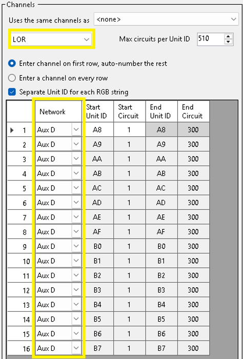
Pictured below is a matrix using 16 controller ports, each with 100 pixels. It’s using a LOR network type and is on network “Aux D”. Because each RGB pixel is 3 channels, each string of 100 will use 300 channels.
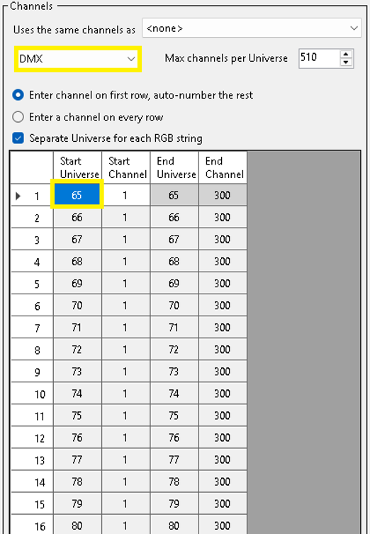
Switch the Prop Definition configuration to DMX by selecting DMX from the drop menu. Review the Start Universe and ensure this value (65 in this example) is an available DMX universe within your configuration. Adjust this value as necessary. Save your prop definition and save your Preview. The prop now uses DMX Universe 65 through 80. This Prop Definition configuration is required to “move” the Prop’s network from the LOR Aux D network to a DMX network. Adjustments are required for each prop/controller to be connected to the PixieLink.
Configuration - Light-O-Rama Control Panel
Once the PixieLink is physically connected to the network, its default IP address is 192.168.1.206. If DHCP is enabled, the PixieLink may obtain another address provided by your router. Once the PixieLink is connected and online, it’s ready to be configured within the Light-O-Rama Control panel.
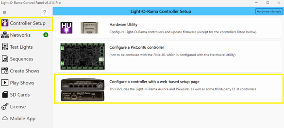
Open the Light-O-Rama Control Panel by clicking Start ► Light-O-Rama ► Light-O-Rama Control Panel. Select the Controller Setup tab and then “Configure a control with a web-based setup page”.
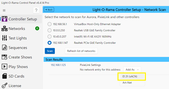
Select the network. Some PCs may have more than one. If the PixieLink was not found after the scan, select a different network and scan again.

Once the PixieLink has been successfully found, it will be listed below the “Scan Results” section. Note the IP address is 192.168.1.125 in this example.

Select the “Add As” drop menu and choose E1.31 (sACN)
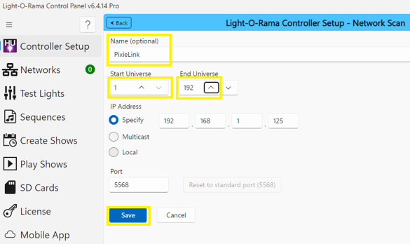
Name the PixieLink as you would like, define its Start and Stop Universe, and click Save. The universe range must include your Preview Prop Definition universes.
Configuration - PixieLink
The PixieLink should not be running a show when configuring it. Configuration is done using a web browser. The factory default host name is “PixieLink” – use http://pixielink in the address bar. Alternatively, the IP address of the PixieLink can be used such as http://192.168.1.111. This address may vary subject to your network configuration and address schema.
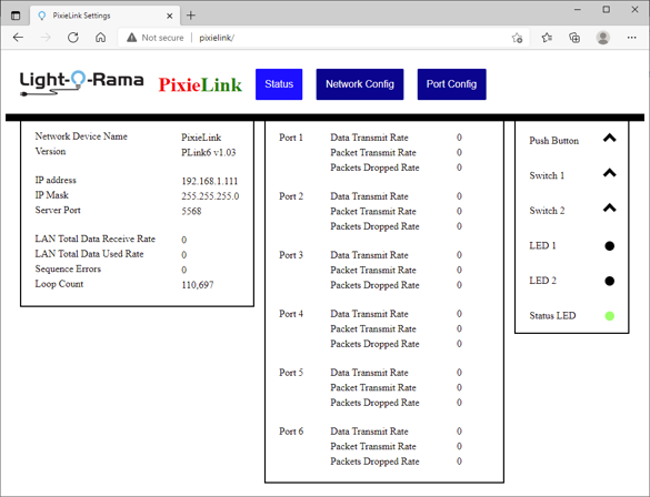
This home screen shows an idle adapter with the Light-O-Rama ShowTime software running.The data rates shown are zero intensity packets being sent.
All data rates are in bytes/second. The LAN Total Data Receive Rate is the number of bytes/second directed to this adapter. The LAN Total Used Rate is the amount of data the adapter is using. They are different because the PC is sending data for 192 universes, but PixieLink may be configured for less.
Sequence errors/second indicate lost/missing packets. It should be zero.
The Loop Count is a measure of adapter busy. It drops as the adapter is forced to do more work.
All Packet rates are in packets/second.

The Network Device Name is registered with the DHCP request. If a fixed IP address is used, it is used as a [NetBIOS] hostname.
Check Enable DHCP if you want the device to try DHCP before using the fixed IP address.
If you are using a fixed IP address, set the IP address and network mask here.
Select the server port for the protocol being used. For LOR use “Standard sACN/E1.31”.
The “Save Configuration” button must be pressed to save the new configuration. It will also write a Network configuration file for the adapter to your download directory. This can be used to upload that configuration with the “Load Configuration” button.
This screen is used to set the port protocol and map universes to pixel strings. In this example, the screen has been made narrow for clarity. Only 3 ports are visible, you must scroll down to see the other 3 ports. You can widen the screen to see all ports at once.
Each port of the PixieLink can be configured for faster PixieLink connectivity (PixieLink, Pixielink8, PixieLink17), Enhanced LOR, or DMX. Click the drop menu for the corresponding port to change the port configuration. Each port contains two columns. The first column corresponds to the Pixie Controller LOR Unit ID and the second column corresponds to the DMX Universe assigned to the LOR Unit ID. Please note the LOR Unit ID here is NOT related to the Prop Definition as the PixieLink converts Prop Definition DMX universe numbers to specific PixieLink ports and LOR Unit IDs.
The drop-down next to the Port number selects the protocol for that port. The options are:
DMX 250Kbps
ELOR19200 Enhanced LOR at 19,200bps
ELOR 57600 Enhanced LOR at 57,600bps
ELOR 115200 Enhanced LOR at 115,200bps
ELOR 500000 Enhanced LOR at 500,000bps
ELOR 1000000 Enhanced LOR at 1,000,000bps
PixieLink Pixielink protocol at 4.25Mbps
PixieLink8 Pixielink protocol at 8.5Mbps
PixieLink17 Pixielink protocol at 17Mbps
The “Pixels:” box allows you to limit the number of pixels/string sent to the Pixies. This can be used to save bandwidth on the ports because E1.31 tends to send full size packets. If you are using 100 pixel strings, these only require 300 intensities/packet rather than the full 510.
To save your port configuration, click the “Save Configuration” button. This will also write a Port Configuration file to your download directory. You can use this file to upload this configuration to any PixieLink adapter. After configuration is complete, click the Save Configuration button.
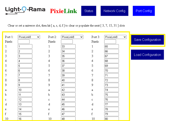
Note Port 3’s configuration uses universes 65 through 80. This corresponds to the earlier Prop Definition adjustments. Each LOR Unit ID in the first Port column corresponds to the Universe ID in the second Port column. A Pixie 16 would be assigned LOR ID 1 for DMX Universe 65 through 80.
Hardware Description
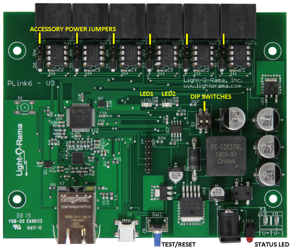
These are used for special conditions. See the Reset button and loading firmware sections.
LAN RJ45 Jack
10/100Mbps LAN port. Auto MDI-X (cross over cable not required).
Left LED – off=10Mbps, on=100Mbps
Right LED – on=Valid link, flashes with activity
LEDs
Status LED – flashes once per second when the PixieLink adapter is up but not connected to an IP network. It is on solid when connected to an IP network. A long on, short off flash sequence means the adapter needs to have its firmware loaded.
LED1 – comes on for 3 seconds and then flashes when the test pattern is being output.
LED2 – flashes once per second when the TCP/IP stack is up.
Light-O-Rama Outputs (RS485 ports)
These six ports have LOR network wiring. They can be connected to LOR controllers using ordinary Cat5/6/7 LAN cables.
There is an internal jumper behind each Output RJ45 jack that allows LOR accessory power to be provided by the jack.
If you are using this device as a DMX bridge, you will need to make crossover cables to change from LOR network wiring to E1.27.
Test/Reset Button
If both DIP switches are ON, press and hold this button when powering up the adapter to reset the configuration to the factory default. Wait until the LED flashes rapidly, then release the test button and the device will reboot with the default configuration.
Press this button momentarily after the adapter has booted to run a simple test pattern on the pixel strings. The test will run until you momentarily press the button again or five minutes go by. The test pattern runs red, then green, then blue down the pixel strings for 100 pixels. This pattern then repeats. The test pattern does not rely on data from the LAN port, or even the current configuration except for the Port Protocol (DMX, ELORnnn, or PixieLinkn).
On a DMX port, the first 100 pixels will run the test pattern. On an Enhanced LOR port or a PixieLink protocol port the first 32 unit IDs will run the test pattern on the first 100 pixels.
Press and hold this button for 5 seconds after the adapter has booted to reboot the adapter. Release the button when the status LED flashes rapidly, the adapter will then reboot.
The adapter disconnects from the IP network or ignores sACN traffic during reboot or when the test pattern is running.
When there is no IP network activity, the adapter will stop sending DMX packets on DMX ports, and it will stop sending heartbeats on Enhanced LOR and PixieLink protocol ports. These actions result in the attached controllers thinking the network has gone away and they will shut down their lights.
*NOTE* Because heartbeats may not be being sent when you momentarily press the test button, the adapter will start sending heartbeats and wait 3 seconds before starting the test pattern. This should give the controllers enough time to lock up at the correct protocol and speed.
USB Port
(future)
Connecting the Adapter to a PC
Ethernet Connection
The PixieLink adapter can obtain an IP address from your router using DHCP, or you can assign it a fixed IPv4 address on your LAN. It is preferable to use a fixed IP address, and configure your show playing software to send the appropriate universes to that IP address.
The easiest way to get the adapter up and running is to allow it to do DHCP to obtain an IP address and then use broadcast in your show playing software. In this case, you do not care what the IP address of the adapter is because all devices on your LAN will see the broadcast messages. If you only have one PixieLink adapter, this method is fine. A maxed out adapter can consume over 40Mbps of your LAN bandwidth, and because of the broadcast, all other devices on your LAN will likely have to process this traffic.
You should change the hostname of the adapter when completing network configuration. You will be able to find the adapter with this name in the address bar of your browser.
Updating the PixieLink Firmware
•Firmware updates done by Hardware Utility versions distributed before September 1, 2020 will be *extremely* slow.
•The adapter is not a normal LOR controller and will respond to Hardware Utility Refresh commands only when in bootloader mode.
•Connect a LOR RS485 adapter to Port 1 on the PixieLink adapter to update firmware.
Get the latest firmware. www.lightorama.com ► Support ► Firmware section. Save the firmware file on your PC. Note where on your PC you have saved the firmware file.
Start the Light-O-Rama Control Panel if it is not running by clicking start ► Light-O-Rama ► Light-O-Rama Control Panel.
Read all steps before proceeding.
Step 1:
Remove PixieLink Power. Connect the PixieLink Port1 to the RS485-USB adapter using an ethernet cable such as Cat5 or Cat6. Ensure the RS485-USB adapter is connected to an available USB port on your PC. Connect PixieLink Port1 to the RS485-USB adapter. Start the Light-O-Rama Control Panel if it is not running by clicking start ► Light-O-Rama ► Light-O-Rama Control Panel. Navigate to the Controller Setup tab. Ensure the COM port for your RS485-USB adapter is selected. Ensure the Scan For section has PixieLink selected.
Step 2:
Power the PixieLink adapter up while holding the test button. It will stay in the boot loader for one minute, or forever if there is no valid application firmware loaded. The status LED flash pattern will be long on, short off, <repeat>. AFTER the PixieLink is in bootloader mode, click Scan for PixieLink. If the PixieLink was not found, ensure Port1 of the PixieLink is connected to the RS485-USB adapter and RS485-USB adapter is connected to the PC then repeat Step 2.

Step 3:
After successfully scanning for the PixieLink, click the configure button
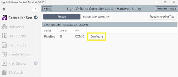
Click Update.
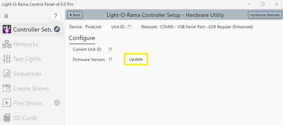
Click Yes to proceed.

Select the PixieLink Firmware and click Open

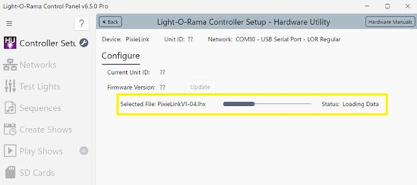
The Update progress bar will fill from left to right. When the new firmware is loaded, the Status will change to “Successful” and the PixieLink adapter will reboot.
DIP Switch Settings
Both switches should be off for normal operation.
Both switches ON and holding the button while powering up will reset the adapter to the factory default configuration. Once the adapter comes up, power it off and turn the switches off.
Specifications
PixieLink sACN Adapter |
|
Configuration |
One 10/100 LAN Port One USB 2.0 port Six RS485 Output Ports |
Power |
9-15vdc @ 1amp |
Operating Temp |
-40º F to 140º F |
Dimensions |
6”w x 1½”h x 4¼”d |