Introduction
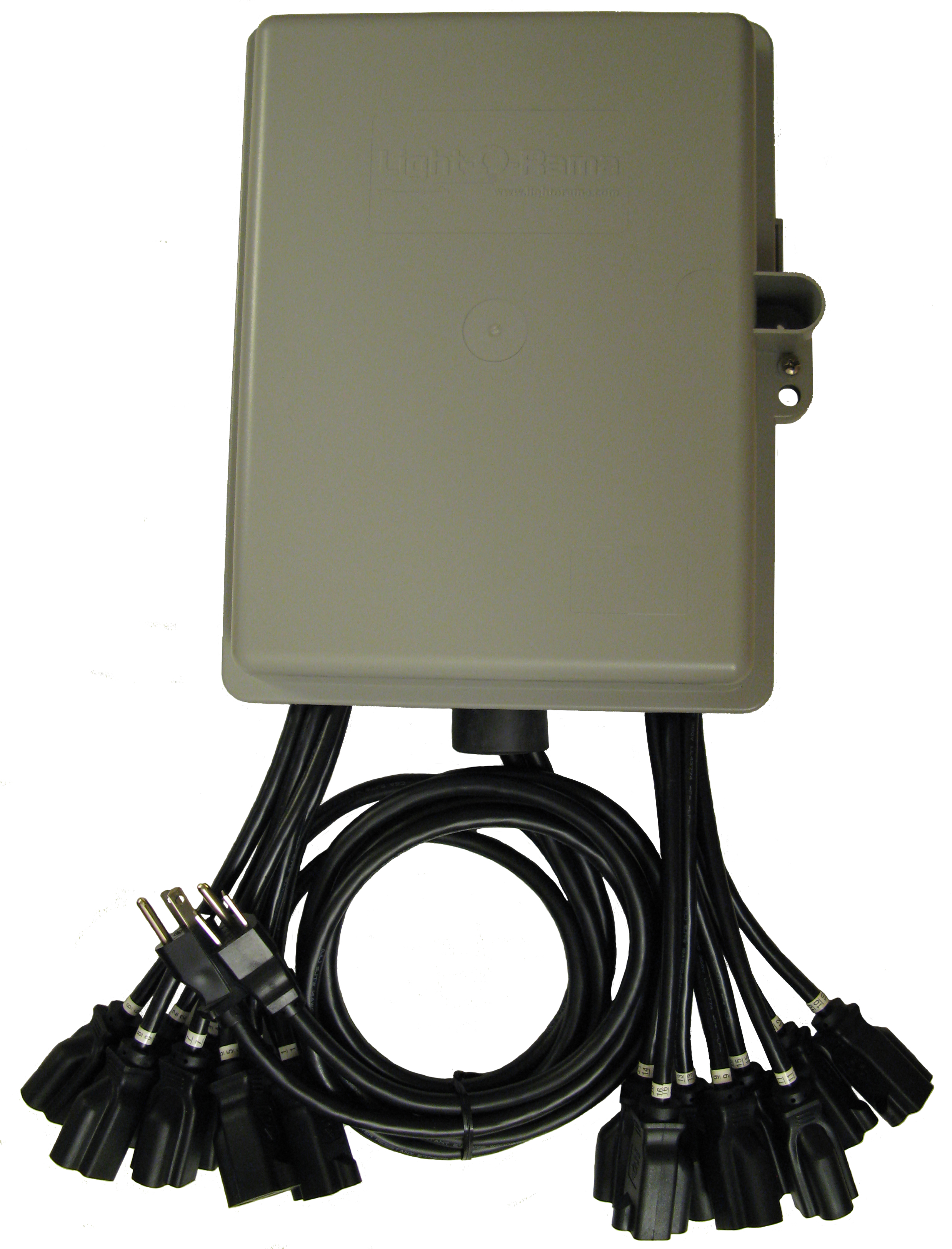
Light-O-Rama (LOR) is proud to bring you the CTB16PCg3. This full function controller was designed with the Christmas lighting enthusiast in mind. It is our most economical controller that sacrifices nothing in terms of the lighting effects. Whether you choose the Ready-To-Go model or one with some manual assembly labor, you will have a full function controller in a weather resistant plastic box.
The CTB16PC is one of the components in the Residential line of Light-O-Rama (LOR) products. It was designed for residential displays. It is a microprocessor based, intelligent controller that can perform a number of lighting effects including dimming, fading, shimmering and twinkling. It can be daisy-chained with any mix of LOR controllers up to the maximum of 240 controllers. Maximum 500K ELOR network speed is supported. All CTB16PC controllers can also be controlled with DMX protocol.
The CTB16PC must be used with the LOR Windows Showtime Software Suite for configuration. This software allows you to configure and test this controller, design your sequences (sequences are lighting control command sets), arrange your sequences into shows and to schedule and play your shows.
To allow your PC to communicate with this controller, you will need one of Light O Rama’s RS485 adapters. When you purchase the Generic Starter Package, you get the LOR Showtime Software, a 10’ Cat5e network cable and a USB RS485 adapter is included. . The RS485 adapter will allow you to connect your PC/laptop via the Cat5e cable to your lighting controller.
This controller is designed to control incandescent and line voltage LED light strings. It operates on 120 VAC (a 240 VAC model is available), 50/60 Hz. It can handle up to 30 amps with the factory heat sinks.. The 30 amp configuration can control approximately 9,000 incandescent mini-lights.
This controller includes “ghost loads” which drain off charge to prevent low brightness LED glow when LEDs should be off.
This controller uses higher reliability triacs (25 amp instead of 16 amp.) These are more tolerant of overloads and even survive some direct short circuit situations.
This controller provides greater accessory power than previous LOR controllers. This additional power will be used by future accessories.
The g3 firmware included with this controller has individual channel lighting curves for smooth, glitch-free dimming and effects with LED lighting. This firmware also increases the number of brightness steps from 250 to 1000 for smoother fading with LEDs.
As with all LOR controllers, this controller is field firmware upgradeable so you are guaranteed compatibility with future LOR hardware and software products.
Contents:
•Reset / Normal Operation Jumper
•Connecting Controller-to-PC Data Cable
•Auxiliary Display & Inputs Header
•Assigning a Unit ID (and DMX address)
•Designing and Playing a Sequence
What’s in the Box
Included is a fully built and tested lighting controller and this user manual. The latest version of this manual is also available at www.lightorama.com ► Support ► CTB16PCg3 User Manual.
The voltage selection jumpers are already set and the “Normal Operation Jumper” is in place. It has been assigned Unit ID 01 at the factory. The process of changing the unit ID is described later in this manual.
Caution: This product requires connection to 120/240 volt AC power. The board has many exposed line voltage connections that are dangerous. Be extremely careful if operating the controller with the box opened during testing.
Lighting Curves
Lighting Curves can be configured within the controller’s configuration. If Lighting Curve adjustments are necessary, it is preferred to use dimming curves within the Prop Definition/Preview editor.
The g3 firmware supports lighting curves. These are used to allow different types of lights to behave similarly when dimming. LEDs tend to go from off to full brightness over a much narrower range of voltages than incandescent lights. This means that a fade going from 0 to 100% voltage with an incandescent light will not produce the same results with LED lights. The LED lights will come on later and reach full brightness sooner than incandescent lights.
There is a built-in Standard curve for incandescent lights which behaves as a simple, linear 0 to 100% voltage provider. This is the behavior seen with previous versions of the firmware and most DMX dimmer packs.
There is a built-in On/Off curve. This on/off ‘curve’ is used on a channel where the connected devices do not tolerate dimming, for example, the air blower motors in inflatables. Setting a channel configured for on/off operation to any intensity 50% or greater results in 100% intensity or ‘on’. Intensities below 50% result in the channel being off.
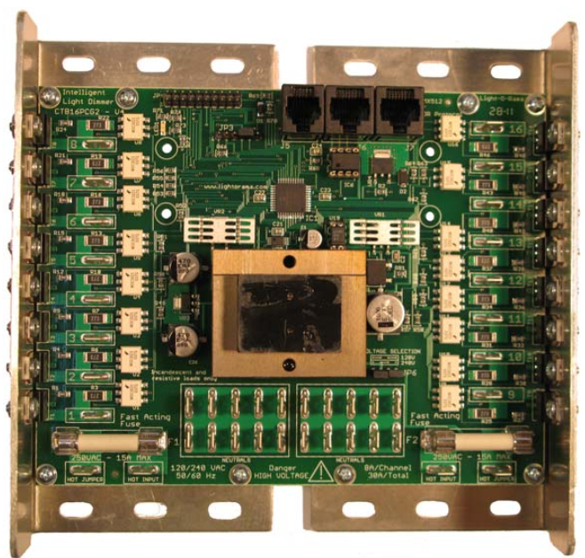
30 amp 120 vac CTB16PCg3 Lighting Controller
Configuring and Testing
Fuses
There are two white fuses located at the left and right bottom of the controller circuit board. The left fuse protects channels 1-8. The right fuse protects channel 9-16. The right fuse also supplies power to the controller electronics. The fuses are 15 amp, fast acting ceramic.
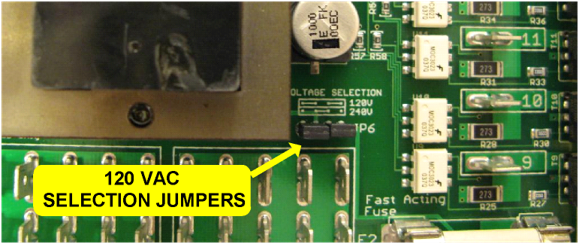
For 120 VAC operation, both jumpers should be installed on the header that is to the lower right of the transformer. See following picture:
*** 240 VAC operation ***
For 240 VAC operation, only one jumper on the center two pins of this header must be installed – AND – the ghost loads must either not be present or of the correct value. Boards configured for 240VAC operation will be marked with a sticker specifying 240VAC operation allowed.
Reset / Normal Operation Jumper
There is a jumper on header JP3. JP3 is the smaller, 6-pin header to the lower left of the network connection jacks. Pin 1 of this jumper is furthest from the network jacks. For normal operation, the jumper is installed between pins 4 & 5 as shown in the following picture:

To reset the controller, power it off, move this jumper to pins 5 & 6 (one pin right) and power the controller on. The status LED will fast blink during reset. Once you see this, power the board off and move the jumper back to pins 4 & 5.
Reset resets everything but the Unit ID, all channels are set to the Standard dimming curve and downloaded dimming curves are deleted.
Connecting Controller-to-PC Data Cable
If you have not installed your RS485 adapter, do it now. The cable from a serial adapter to the first controller is limited to 100’ or less.
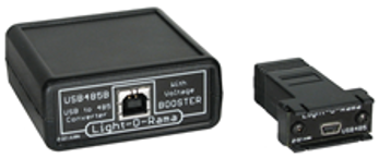
If you have one of the USB adapters, follow the installation instructions that came with the adapter.
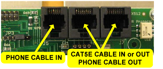
If you are using Cat5/6 cable to connect your controller to the RS485 adapter, plug one end of the data cable into the adapter and the other end into either of the CAT5E CABLE IN or OUT jacks shown in the previous picture. It is not recommended to use the phone cable IN jack.
Auxiliary Display & Inputs Header
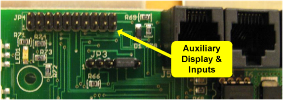
This 20-pin header located on the upper left of the controller circuit board provides for an auxiliary display card and interactive trigger inputs. The input Header is available from the Light-O-Rama Store.
20-Pin Header Diagram:
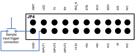
The diagram above shows a sample connection for one of the trigger inputs. Do not apply voltages to any pins. The trigger inputs must be simple switch closures. The +9vdc pin may be used to power accessories like motion detection switches. No connections should be made to pins other than GND, INPUT or +9V.
Assigning a Unit ID (and DMX address)
If you have not installed the Light O Rama Windows Showtime Software, do it now.
The board will need to be powered at this point – BE VERY CAREFUL – there are dangerous voltages present on the exposed circuit board. Take appropriate precautions with children and pets.
Plug the CTB16PC power cord(s) into AC power. The LED on the upper left will blink about twice/second. This means that the board has booted and is waiting for the PC to talk to it. Connect the controller to your PC – see the Connecting Controller-To-Pc Data Cable section.
Start the Hardware Utility – click start ► All Programs ► Light-O-Rama ► Light-O-Rama Control Panel. You will see the following window:
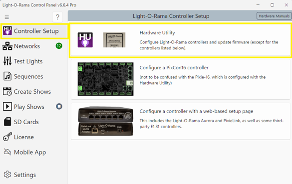
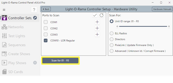
Select the Controller Setup Tab, then the Hardware Utility Section. The Hardware Utility will search for the COM port that your RS485 adapter is plugged into and select it. Click the “Scan for” button to search for the connected controller.
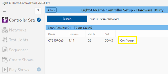
Click the “Configure” button to change controller settings.
Click the “Change” button to change the controller Unit ID.
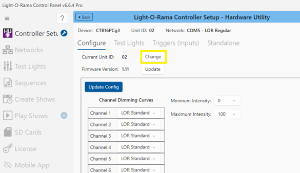
When assigning a unit ID, only one controller should be plugged into the RS485 adapter on the PC. Be sure you do not have more than one controller connected.
Choose a Unit ID within the “New Unit ID” and click change. Once the ID changes, click “Ok”
The DMX address is set to (Unit ID – 1) * 16 + 1.
Each Unit ID occupies 16 DMX addresses:
Unit ID 1 would use DMX addresses 1-16 where 1 is the DMX starting address.
Unit ID 2 would use DMX addresses 17-32 where 17 is the DMX starting address.
Your CTB16PC is ready for testing.
Testing the CTB16PC
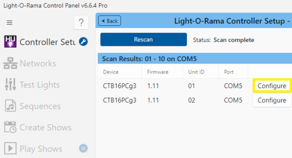
In the Scan For section of the Hardware Utility window,. move the slider in the Scan For box so that the Unit ID range is set to 10 (or the maximum number of controllers you have configured.) This will limit the search for controllers to the first 10 unit IDs, otherwise 240 controllers would be searched for – taking a long time. Click the Scan for button.
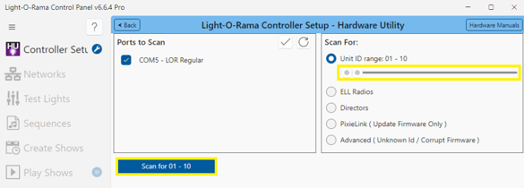
Select the controller you want to test by clicking on the corresponding Configure button.
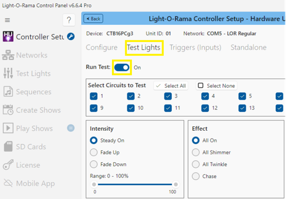
Select the Test Lights tab. Plug some lights into your controller and use the check boxes and sliders in this section to test your controller.
Designing and Playing a Sequence
Lighting commands for your shows are called Sequences and are designed and implemented using the Sequence Editor Windows software.
There are Quick Start Guides for creating animation (non-musical) and musical sequences, Flash Tutorials and much more at:
www.lightorama.com ► Video Tutorials
There is also a very active and helpful Light-O-Rama user community at:
facebook.com/groups/lorofficial
Status LED
LED blinking approximately twice/second: Controller has booted correctly and is waiting for commands. The controller is not connected to a Light O Rama network or the network is not active.
LED is on solid: Controller is connected to an active network (is receiving the heartbeat and commands from a PC or a Show Director)
LED is blinking fast: The normal operation jumper is not on JP3, the controller is resetting. See the section on Reset / Normal Operation Jumper for placement of the jumper.
LED is not on at all: There is no power to the right side of the controller, verify power source with a working lamp. The right fuse is blown – power the controller off and swap the left and right fuses or try a new fuse on the right side.
Updating Controller Firmware
Periodically, Light-O-Rama will distribute new firmware for your CTB16PCg3. If you believe you need updated firmware, use the Hardware Utility to determine your current firmware version. Use the Scan for button to find your controller and check its firmware version. After scanning for controllers, the firmware version is listed with each corresponding controller.
The latest firmware can be found by going to www.lightorama.com ► Resources ► Firmware Updates Find your controller and roll the mouse over the Download button – look at the bar in the lower left of the browser window. It will show the name of the firmware file. The file name contains the version at the end. If the version number is greater than what you saw in the Hardware Utility, new firmware is available. Click the Download button to download the firmware to your PC – remember where you put it.
To load new firmware, use a data cable (not wireless) to connect the controller(s) to the PC. Open the Light-O-Rama Control Panel, select the Controller Setup tab, and the Hardware Utility.
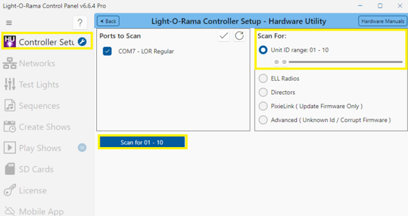
Select the Scan For option. If the controller ID is known, adjusting the range of the Scan For Option slider can reduce controller scanning time. Click the Scan for button After scanning, select the controller using the Configure button next to the corresponding controller. Click the Update button to select the firmware file.
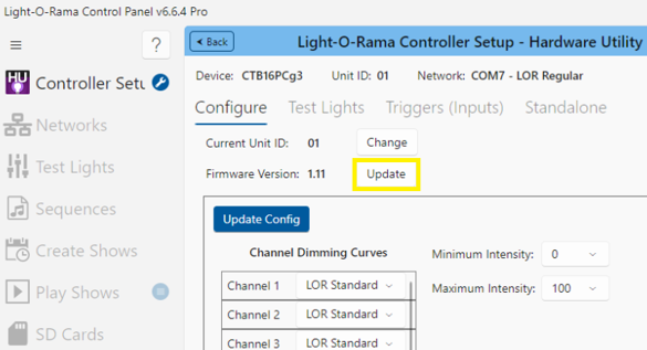
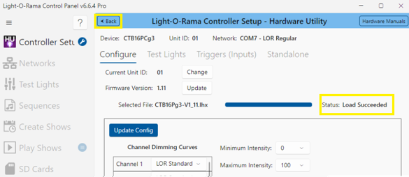
Select the correct firmware file that matches the controller and click Open. Firmware has been updated when the status says “Load Succeeded”. Click the back buttons to exit the Hardware utility.
Specifications
Configuration |
Two banks of 8 channels |
Individual Channel Capacity |
1 amp – No Heat Sinks 8 amps – Regular Heat Sinks |
Individual Bank Capacity |
8 amps – No Heat Sinks 15 amps – Regular Heat Sinks |
Board Capacity Single Power Feed |
15 amps – No Heat Sinks 15 amps – Regular Heat Sinks |
Board Capacity Dual Power Feed |
16 amps – No Heat Sinks 30 amps – Regular Heat Sinks |
Supply Voltage (two separate models) |
120 VAC, 50/60 Hz 240 VAC, 50/60 Hz |
Fuses |
15 amp fast acting |
Isolation |
Optos isolate line voltage from control logic |
Power Connections |
Quick connects (spade lugs) |
No Heat Sinks |
6 ¾”w x 5 ¼”h x 1 ½”d |
Regular Heat Sinks |
7 ¼”w x 6 ¾”h x 2 ¼”d |
Plastic enclosure |
9 ½”w x 11 ½”h x 3 ½”d |